Self-cleaning influent feed system for a wastewater treatment plant

a wastewater treatment plant and influent technology, applied in the field of systems, can solve problems such as stream velocities reduction, and achieve the effects of increasing the percent solids in the sludge, minimal cross section of the liquid in the tank, and increasing the influent velocities

Active Publication Date: 2010-05-06
TRANS TERRA CORP
View PDF14 Cites 11 Cited by
  • Summary
  • Abstract
  • Description
  • Claims
  • Application Information

AI Technical Summary

Benefits of technology

[0017]Briefly described, the present Influent Feed System (IFS) directs and distributes the energy given to the influent liquid by gravity to scour the surface of the tank walls and the inclined tank base and to move the scoured solids to a sludge trough, also referred to herein as a sludge hopper. This scouring action takes place preferentially during periods of low liquid levels in the tank because the height of fall

Problems solved by technology

This collision results in turbulence

Method used


Image

  • Self-cleaning influent feed system for a wastewater treatment plant
  • Self-cleaning influent feed system for a wastewater treatment plant
  • Self-cleaning influent feed system for a wastewater treatment plant

Examples


Embodiment Construction

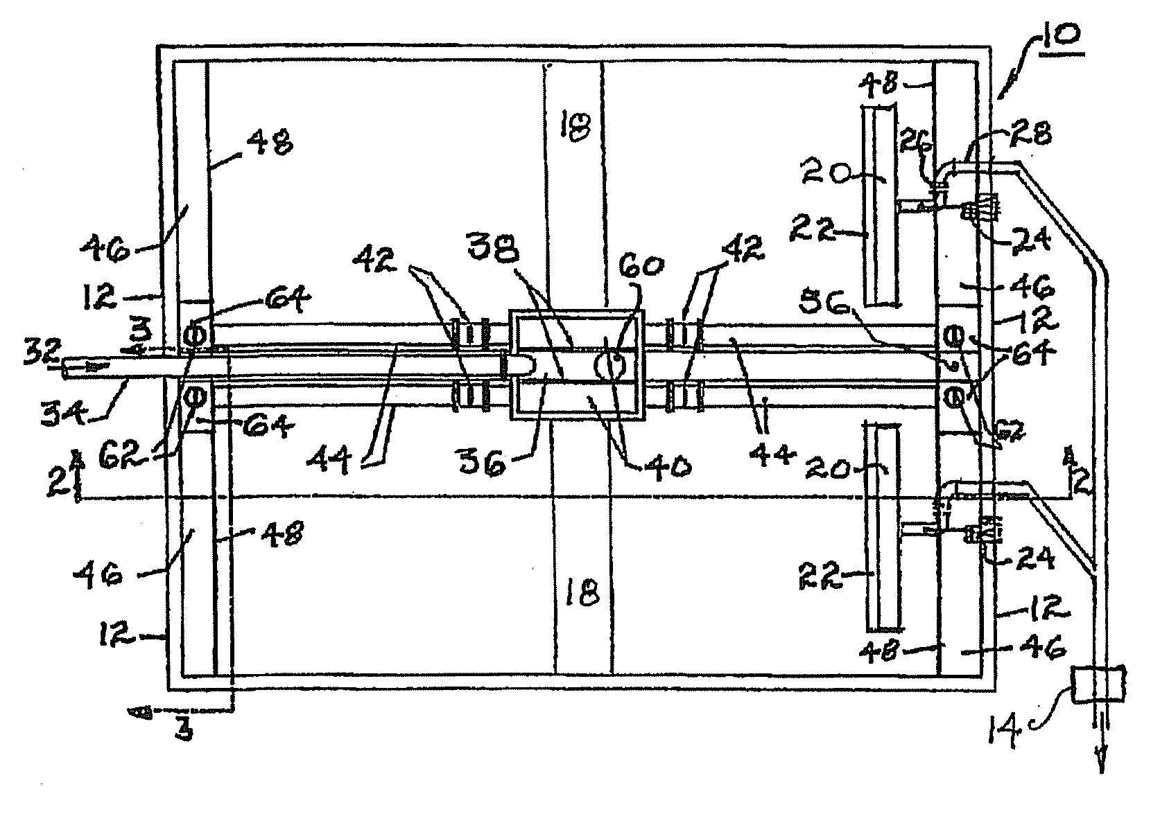
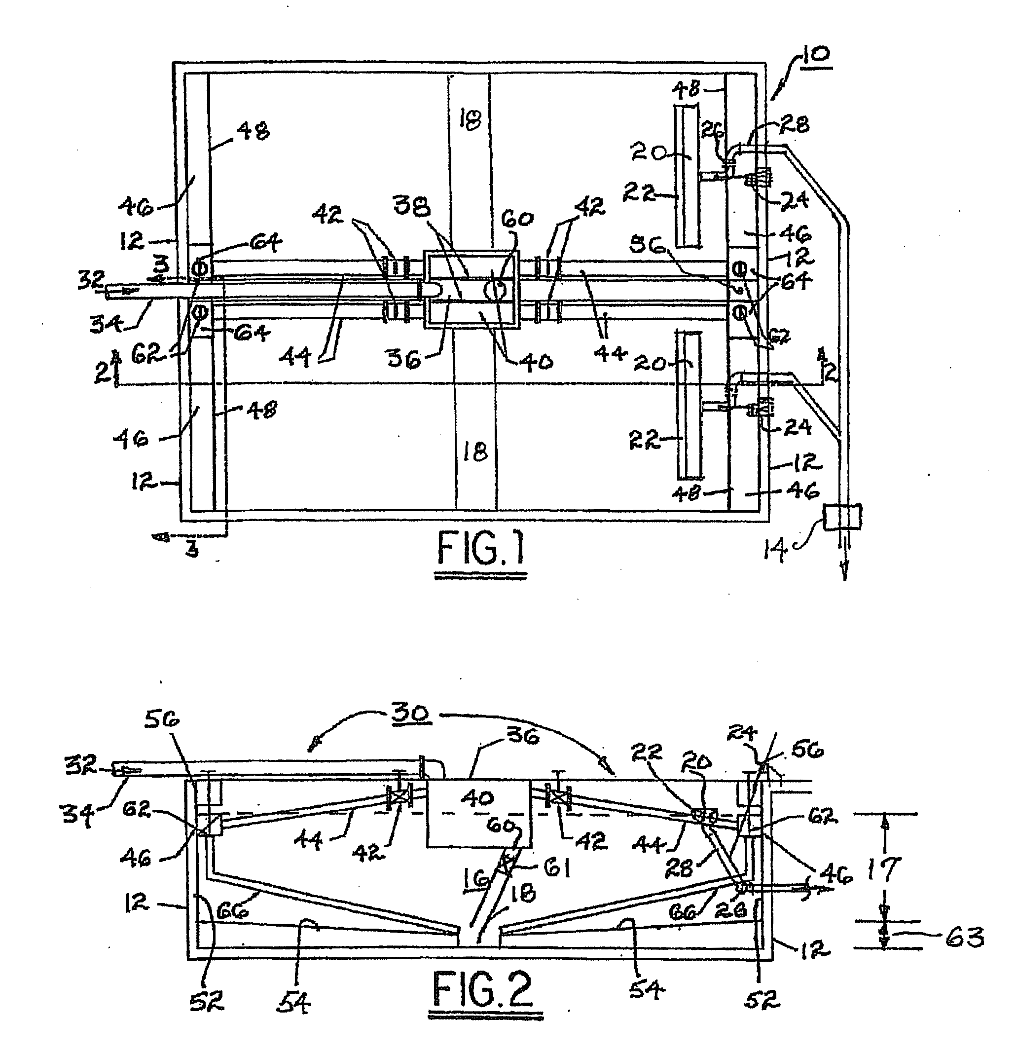
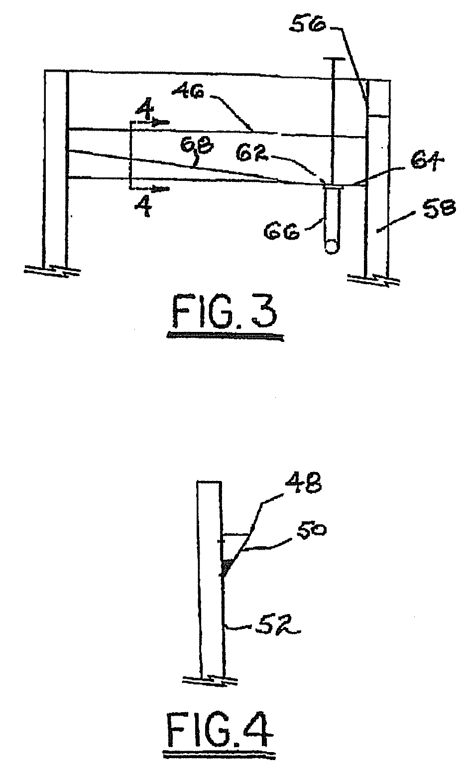
[0029]Referring to FIGS. 1 through 4, a system 10 for the primary treatment of wastewater streams (including grit removal, flow equalization, fine screening, flow measurement, and primary clarification) comprises at least one tank 12 and preferably two identically-equipped mirror-image tanks 12 as shown in FIG. 1. The following discussion deals primarily with only one of the two tanks 12 but should be taken as applying equally to both tanks 12 except as noted.

[0030]The overall treatment of waste water influent is substantially as disclosed in the parent '553 application. A flow measurement device 14 is located on the discharge side of the primary settling tanks 12 to measure the actual effluent flow from the primary settling tank. Further, an air blower (not shown) may be provided to aerate the waste water 16 in the primary settling tank to prevent the waste water from becoming septic.

[0031]The waste water treatment system also includes at least one sludge trough 18, a scum trough (...


PUM

PropertyMeasurementUnit
Dimensionaaaaaaaaaa
Gravityaaaaaaaaaa

Abstract

An influent feed system for directing the influent liquid via hydraulic energy to scour the surface of primary treatment tank walls and base to move the scoured solids to a sludge trough. Scouring action takes place during periods of low liquid levels in the tank. The system comprises two identical, adjacent tanks sharing a common distribution box. Either or both of the tanks are in use at any given time. The tank in use will be empty occasionally each day. Influent feed troughs disposed transversely in each tank directs solids towards a sludge hopper in the tank bottom. The IFTs extend over the width of the tank to provide scouring of the entire end wall and floor surface. Each IFT has a sump with a valved discharge piped directly to the sludge trough, and the floor of each IFT is sloped towards the sump to facilitates draining of solids.

Description

CROSS-REFERENCE TO RELATED APPLICATIONS[0001]This application is a Continuation-In-Part of a pending U.S. patent application Ser. No. 12 / 177,553, filed Jul. 22, 2008.BACKGROUND OF THE INVENTION[0002]The present invention relates to a system (apparatus and methods) for treatment of waste water streams; more particularly to a system for the primary treatment of waste water streams, including grit removal, flow equalization, fine screening, flow measurement, and primary clarification; and most particularly to a system for performing such functions in a single primary settling tank, wherein the tank is made to be self-flushing of settled solids on the tank walls and floor by the hydraulic force of the influent waste water stream.[0003]Prior art waste water treatment systems used in the industry generally include, but are not limited to, the following treatment processes: grit removal, fine screening, flow equalization, and primary clarification. The typical treatment processes are depen...

Claims


Application Information

Patent Timeline
IPC IPC(8): B01D21/02C02F1/00
CPCB01D21/0006B01D21/0012B01D21/2405C02F2001/007B01D21/2444B01D21/34B01D21/2427B01D21/02B01D21/24C02F1/00
Inventor WRIGHT, TERRY
Owner TRANS TERRA CORP
Why Eureka
Try Eureka