Cooling device for cooling a winding braid of an electrical machine and method for retrofitting the electrical machine with the cooling device

a cooling device and winding braid technology, which is applied in the direction of cooling/ventilation arrangement, dynamo-electric components, supports/encloses/casings, etc., can solve the problem of winding braid thermal overload risk

Active Publication Date: 2014-02-27
SIEMENS ENERGY GLOBAL GMBH & CO KG
View PDF3 Cites 1 Cited by
  • Summary
  • Abstract
  • Description
  • Claims
  • Application Information

AI Technical Summary

Benefits of technology

[0005]The object of the invention is to create a cooling device for cooling an air-permeable winding braid of an electrical machine, an electrical machine comprising the cooling device, and a method for retrofitting the electrical machine with the cooling device, wherein the winding braid and therefore the electrical machine are cooled effectively.
[0007]The winding braid comprises an end crown connection, and the surface of the baffle is preferably formed in such a way that the channel has a cross section minimum in the region of the end crown connection. Since, at the end crown connection, the winding braid is subject to high thermal load during operation of the electrical machine, it is advantageous for the stream of cooling air to flow through the channel at a high speed obtained by means of the cross section minimum, whereby the cooling of the region of the end crown connection of the winding braid is effective as a result of corresponding convection effects.
[0009]The stream of cooling air conveyed by the fan impacts substantially perpendicularly against the first surface portion on the first-mentioned side of the winding braid. Since the winding braid is air-permeable, a part of the stream of the cooling air can penetrate the winding braid. The flow through the winding braid is subject to flow resistance, whereby a pressure drop is to be observed in the direction in which air flows through the winding braid. When the stream of cooling air impacts against the winding braid, one partial stream swerves and flows along the surface of the winding braid, wherein the other partial stream of the cooling stream penetrates the winding braid. The partial stream flowing along the surface of the winding braid enters the channel and is guided by the baffle substantially parallel to the surface of the second surface portion of the winding braid. Due to the continuity condition, the flow rate of the partial stream in the channel is determined by the distance between the baffle and the second surface portion. In accordance with the invention, the distance between the baffle and the second surface portion, and therefore the width of the channel, is to be selected such that a formation of a return flow area when the partial stream penetrating the winding braid exits is prevented on the other side of the winding braid that faces away from the first-mentioned side. This is achieved in that, with an accordingly high speed level and an accordingly high mass flow rate of the partial stream in the channel, the partial stream when exiting from the channel has high kinetic energy, in such a way that a return flow area on the cooling air exit side of the winding braid cannot form. If, in contrast thereto, the speed level in the channel or the mass flow rate and therefore the kinetic energy of the partial stream exiting from the channel were too low, turbulence for example could thus be formed and driven by the partial stream exiting through the winding braid and, in the form of eddying areas, could hinder a dissipation of heat from the winding braid through the stream of cooling air. Since, due to the cooling device according to the invention, the formation of eddying areas at the winding braid is prevented, the winding braid is cooled effectively by the cooling device.
[0010]It is preferable for the contour of the surface of the baffle that faces the winding braid to be based on the contour of the second surface portion on the first-mentioned side of the winding braid. The speed level over the flow length in the channel is thus approximately constant, whereby the dissipation of heat from the winding braid is substantially uniform along the channel. In addition, it is preferable for the fan to comprise a fan casing, by means of which the fan is encased and in which the stream of cooling air is conveyed by the fan, and for the baffle to comprise an inlet profile portion, which is arranged between the fan casing and the surface of the baffle facing the winding braid, such that a partial stream of the cooling stream is deflected by the inlet profile portion into the channel without transfer. The stream of cooling air is thus guided with little loss from the fan casing to the channel, wherein an accordingly advantageously high speed level is present at the channel entry. In addition, any turbulences in the inflow region are suppressed and would otherwise lead to a reduction of the stream of cooling air, whereby the efficacy when cooling the winding braid would be reduced.

Problems solved by technology

In particular, there is a risk due to the ohmic losses of overheating in the region of the end crown connection of the winding head, whereby high demands are placed on the cooling device for cooling the winding head in the region of the end crown connection.
In this case, it is problematic however that a hotspot of the winding braid may develop, in particular in the region of the end crown connection, whereby there is a risk of thermal overload of the winding braid in the region of the end crown connection.

Method used


Image

  • Cooling device for cooling a winding braid of an electrical machine and method for retrofitting the electrical machine with the cooling device
  • Cooling device for cooling a winding braid of an electrical machine and method for retrofitting the electrical machine with the cooling device
  • Cooling device for cooling a winding braid of an electrical machine and method for retrofitting the electrical machine with the cooling device

Examples


Embodiment Construction

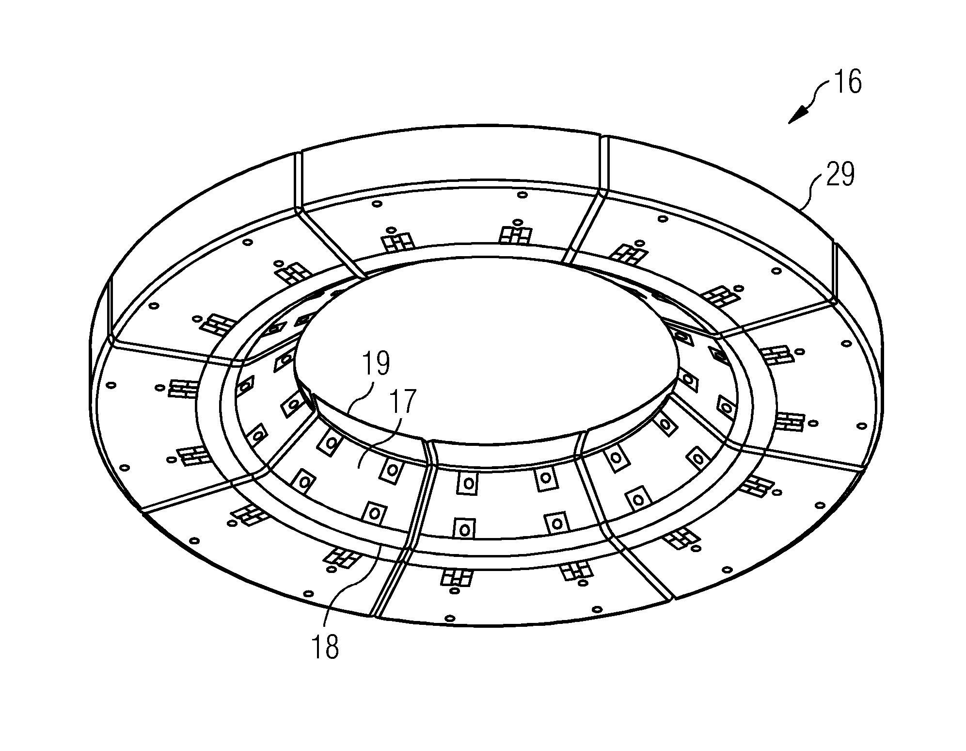
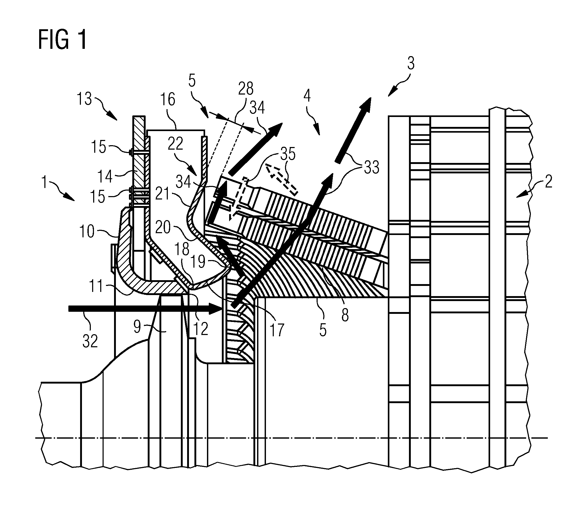
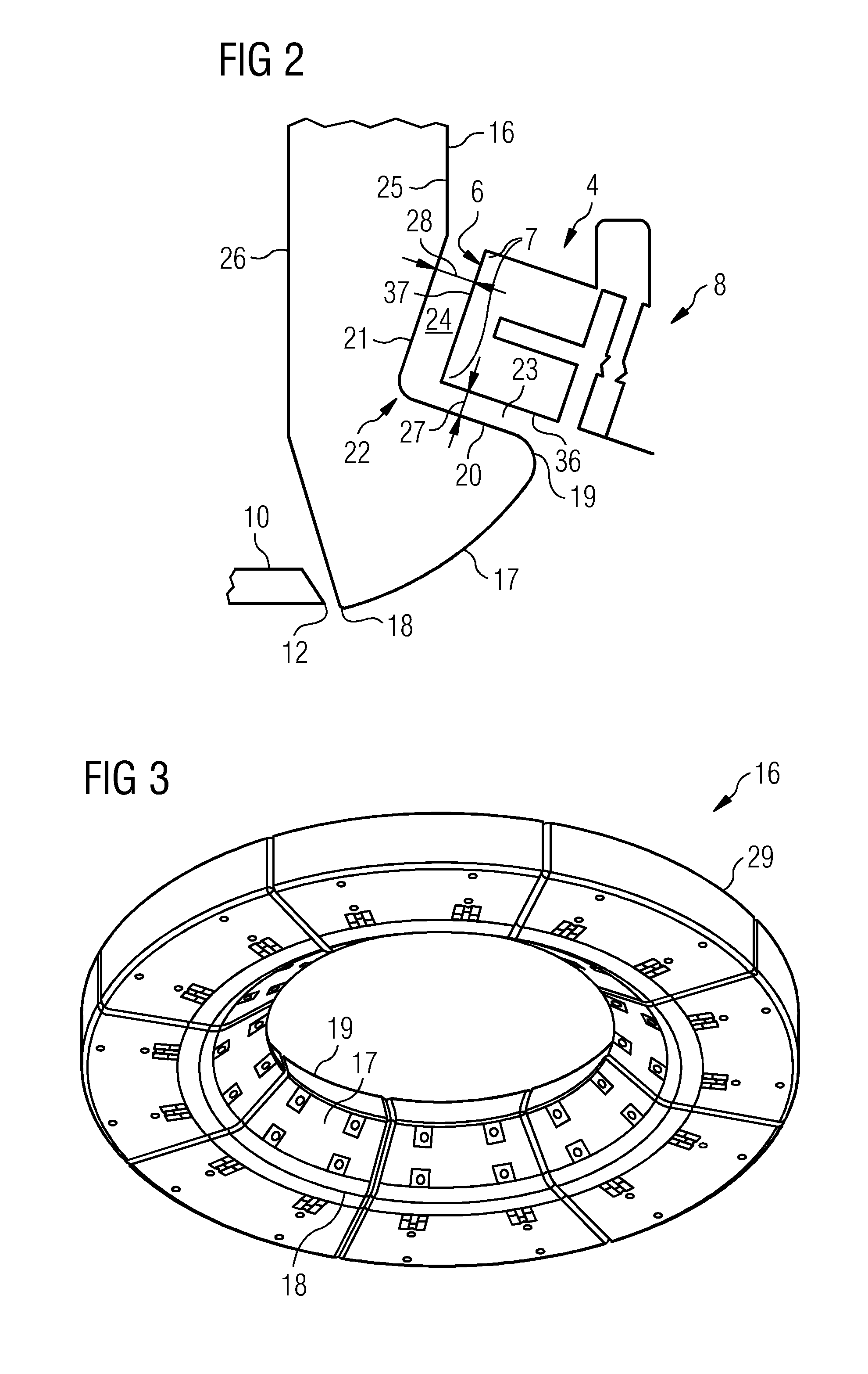
[0020]As can be seen from FIGS. 1 to 6, a generator 1 comprises a stator 2, which is equipped with a stator winding, which is formed by an air-permeable winding braid 3. The stator 2 with its stator winding is formed rotationally symmetrically about the machine axis of the generator 1, wherein, at its end face, the winding braid 3 comprises a rotationally symmetrical winding head 4. The winding braid 3 is formed by a winding conductor 5 or a plurality winding wires 5, wherein the winding conductors 5 or the winding wires 5 are wound to form the winding braid 3. The winding head 4 forms an end face 6 of the winding braid 3, on which an end crown connection 7 and an involute 8 of the stator winding are arranged.

[0021]The generator 1 is air-cooled, wherein a fan 9 is provided for this purpose. The fan 9 comprises a blade wheel, which is rotatable about the machine axis of the generator 1 and is formed by a plurality of identically shaped axial blades arranged equidistantly over the per...


PUM

PropertyMeasurementUnit
distanceaaaaaaaaaa
temperature resistanceaaaaaaaaaa
speedaaaaaaaaaa

Abstract

A cooling device for cooling an air-permeable winding braid of an electrical machine is provided. The cooling device includes a baffle and a fan, which is arranged for blowing a stream of cooling air substantially perpendicularly onto a first surface portion of one side of the wind braid, wherein, in the region of a second surface portion of the side of the winding braid, arranged alongside the first surface portion, the baffle is arranged substantially parallel to and that a distance from the surface of the second surface portion such that a partial stream of the stream of cooling air is formed in the channel that is formed by the baffle and the second surface portion, and so, on the side of the winding braid that is opposite from the first-mentioned side, the other partial stream of the stream of cooling air, penetrating the winding braid, flows away from the winding braid without any return flow.

Description

CROSS REFERENCE TO RELATED APPLICATIONS[0001]This application is the US National Stage of International Application No. PCT / EP2012 / 054860 filed Mar. 20, 2012 and claims benefit thereof, the entire content of which is hereby incorporated herein by reference. The International Application claims priority to the European Patent Office application No. 11162657.8 EP filed Mar. 15, 2011, the entire contents of which is hereby incorporated herein by reference.FIELD OF INVENTION[0002]The invention relates to a cooling device for cooling an air-permeable winding braid of an electrical machine, to the electrical machine comprising the cooling device, and to a method for retrofitting the electrical machine with the cooling device.BACKGROUND OF INVENTION[0003]An electrical machine, for example a generator, comprises a stator with a stator winding. The stator winding is conventionally formed by winding conductors, wherein the winding conductor is formed into an air-permeable winding braid. The s...

Claims


Application Information

Patent Timeline
Patent Type & Authority Applications(United States)
IPC IPC(8): H02K9/04H02K15/00
CPCH02K15/00H02K9/04H02K3/24Y10T29/49009H02K5/207
Inventor BANDA, MARCUSCHEN, ZHIYNMICHELSSON, OLAF
Owner SIEMENS ENERGY GLOBAL GMBH & CO KG
Why Eureka
Try Eureka