

Pin for fixing an implant subjected to tensile load
Patent Information
- Authority / Receiving Office
- US · United States
- Patent Type
- Patents(United States)
- Current Assignee / Owner
- KARL STORZ GMBH & CO KG
- Publication Date
- 2012-10-16
- Estimated Expiration
- Not applicable · inactive patent
Smart Images
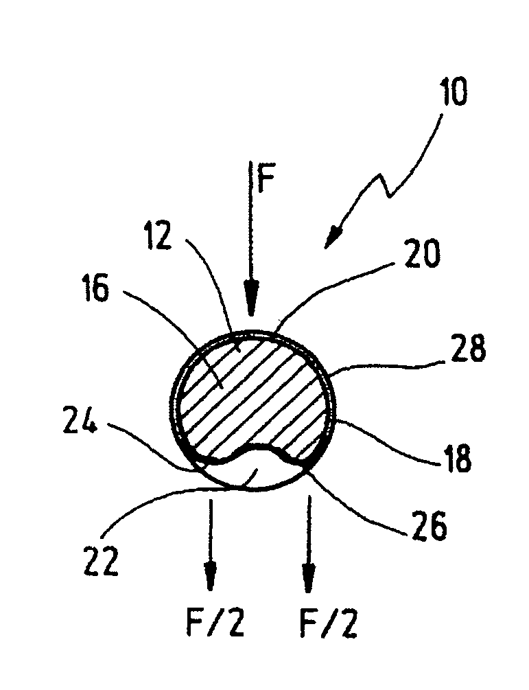
Figure 1 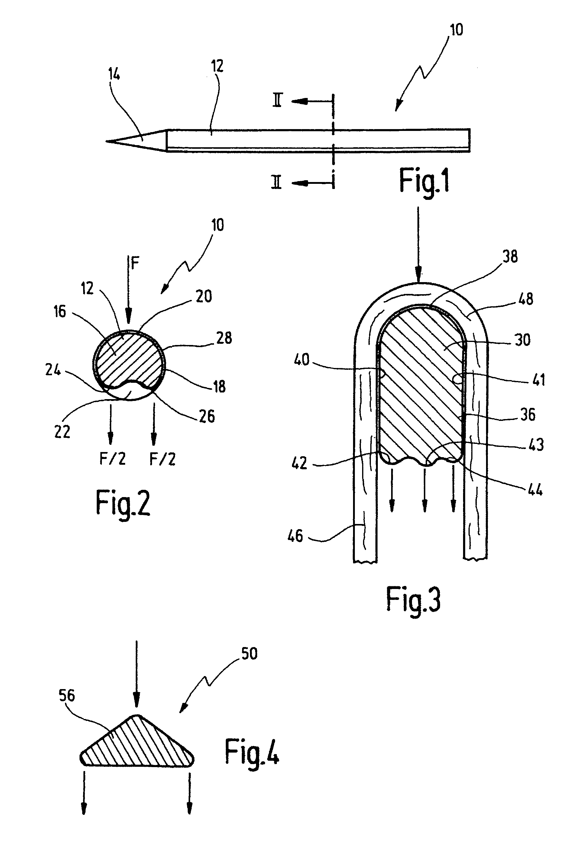
Figure 2 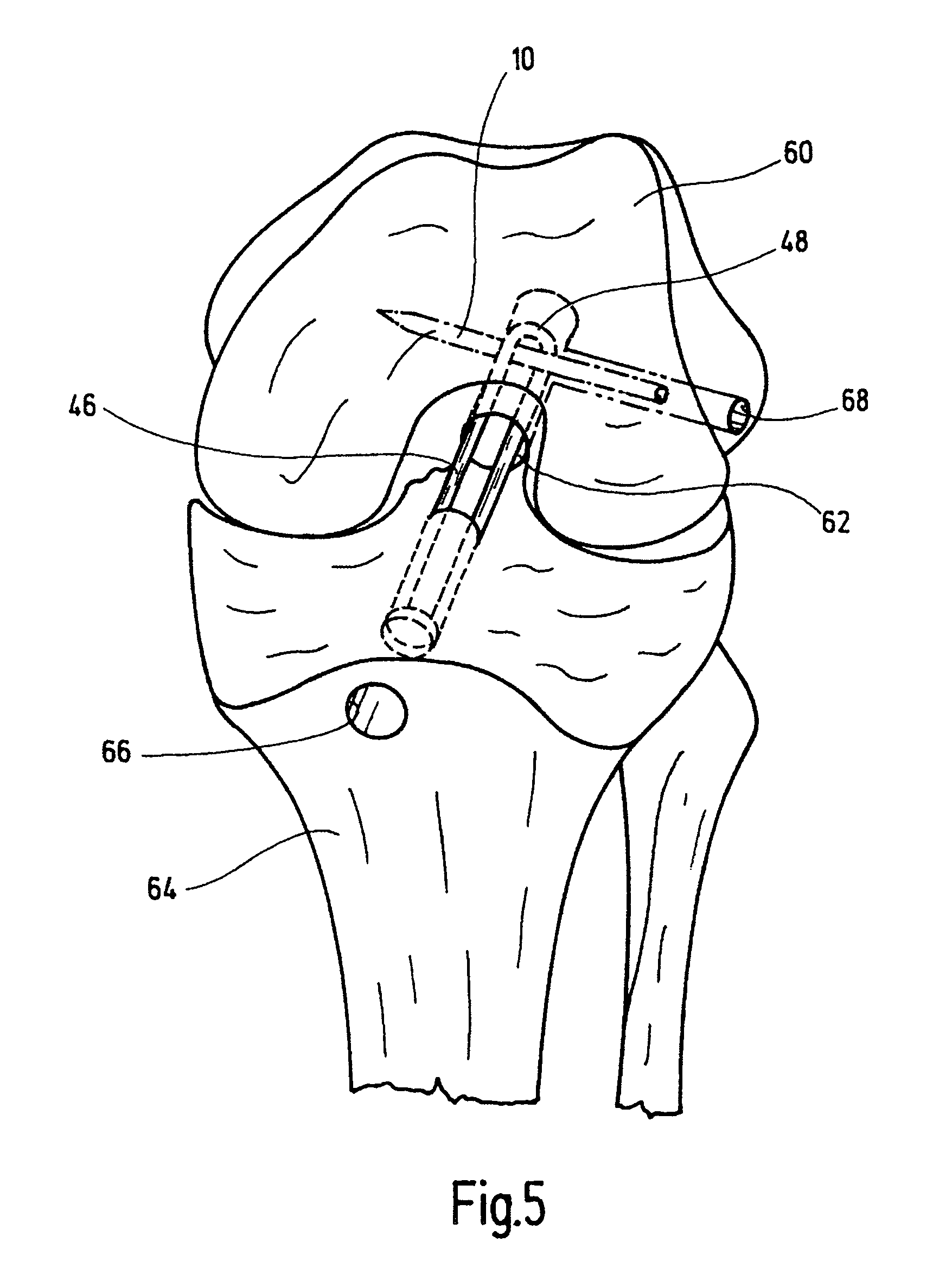
Figure 3
Abstract
Description
PRIOR APPLICATIONS
[0001] This application claims priority of German Patent Application No. 10 2004 053471.3 filed on Nov. 3, 2004.FIELD OF THE INVENTION
[0002] The invention relates to a pin for fixing an implant subjected to tensile load, in particular a tendon implant, said pin having a rod-shaped body, a force exerted by the implant being able to be input onto a cross section of the pin, on one side, and being able to be output on an opposite side to an anchoring site.BACKGROUND OF THE INVENTION
[0003] Pins of this kind are used to fix an implant fitted in an opening in a bone. To do this, the implant is first pushed into the opening, in most cases a bore that has been formed from the outside. The pin is then driven in transversely thereto, thus passing transversely through the bore and through the implant pushed into the latter, as a result of which said implant is fixed in position. Since the pin extends transversely with respect to the longitudinal extent of the implant, the expres...