Grouting combined mould

A combined mold and grouting technology, used in die-casting molds, manufacturing tools, ceramic molding machines, etc., can solve the problems of low grouting molding efficiency, high production cost, low utilization rate of gypsum molds, etc., and achieve good splicing efficiency and connection. Large contact surface and easy connection

Inactive Publication Date: 2015-11-11
CHONGQING XINSHENG CERAMICS
View PDF7 Cites 7 Cited by
  • Summary
  • Abstract
  • Description
  • Claims
  • Application Information

AI Technical Summary

Problems solved by technology

The disadvantage of this structure is that two gypsum molds can only form one ceramic product at a time, and four gypsum molds can produce two ceramic products with a single grouting, which will lead to low efficiency of grouting molding on the production line and lower utilization rate of plaster molds. Not high, high production cost

Method used


Image

  • Grouting combined mould

Examples


Embodiment Construction

[0013] The present invention will be described in further detail below by means of specific embodiments:

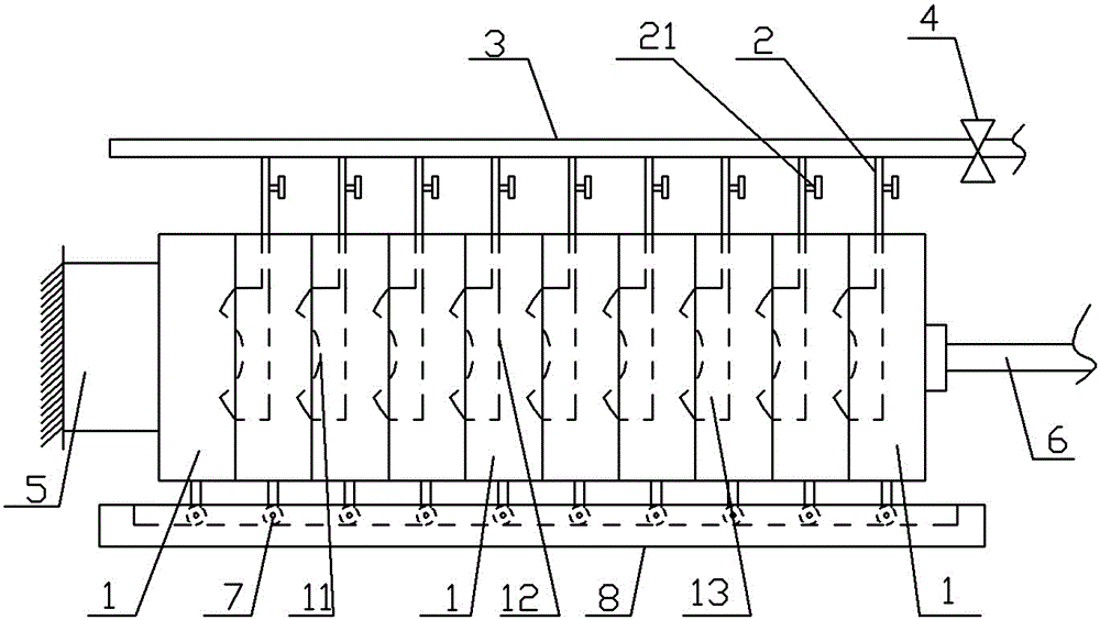
[0014] The reference signs in the drawings of the description include: plaster mold 1, bump 11, groove 12, mud forming cavity 13, grouting branch pipe 2, grouting valve 21, mud pipe 3, mud pump 4, limit block 5, Cylinder output shaft 6, roller 7, guide rail 8.

[0015] Embodiment The grouting combined mold is basically as attached figure 1 Shown:

[0016] The combined plaster mold for grouting includes ten plaster molds 1 that are joined together. Among any two adjacent plaster molds 1, the plaster mold 1 on the left has a bump 11, and the plaster mold 1 on the right has a bump 11. The groove 12 opposite to the bump 11 forms a mud molding cavity 13 between the bump 11 and the groove 12. The plaster mold 1 with the groove 12 is provided with a grouting port communicating with the mud molding cavity 13. The grouting The mouth is connected with the grouting branch pipe 2,...


PUM


Abstract

The invention belongs to the technical field of grouting molding of ceramic products, and discloses a grouting combined mould. The grouting combined mould comprises a plurality of plaster moulds, and slurry molding cavities are formed between adjacent plaster moulds; each slurry molding cavity is connected with an independent grouting branch pipe, and the multiple grouting branch pipes are connected to slurry pipes with slurry pumps; a guide rail is arranged on the lower portions of the plaster moulds, and rollers matched with the guide rail are arranged at the bottoms of the plaster moulds; and in the multiple plaster moulds, the left side of the plaster mould located at the left end abuts against a limiting block, and the right side of the plaster mould located at the right end is fixedly connected with an air cylinder output shaft. The grouting combined mould is formed by splicing the multiple plaster moulds, the slurry molding cavities between the adjacent plaster moulds can complete grouting molding, and three plaster moulds can complete grouting molding of two ceramic products. Compared with a manner that four original plaster moulds carry out grouting to form two ceramic products at a time, the grouting combined mould is higher in efficiency, and the plaster moulds can be fully utilized.

Description

technical field [0001] The invention belongs to the technical field of grouting molding of ceramic products. Background technique [0002] Ceramics refer to various products made from clay and other natural minerals through crushing, molding, roasting and other processes. Ceramics include daily-use ceramics, chemical ceramics, building ceramics and other industrial ceramics, especially daily-use ceramics. Ceramics are closely related to our daily life. [0003] Daily-use ceramics include ceramic basins, ceramic bathtubs, ceramic toilets, etc. The main steps of the production process of daily-use ceramics are: raw material preparation—ball milling into slurry—forming and drying—glazing and drying—firing—inspection, Among them, the molding of ceramics usually adopts the grouting molding method. The grouting molding method is to inject the prepared mud into the gypsum mold, the water in the mud is gradually absorbed by the gypsum mold, and the mud forms a green body. When the...

Claims


Application Information

Patent Timeline
Patent Type & Authority Applications(China)
IPC IPC(8): B28B1/26B28B7/34
CPCB28B1/26B28B1/261B28B1/264B28B7/344
Inventor 曹华林
Owner CHONGQING XINSHENG CERAMICS
Why Eureka
Try Eureka