Hollow shaft arrangement

a technology of hollow shafts and shafts, applied in the direction of magnetic circuit rotating parts, magnetic circuit shape/form/construction, vehicle sub-unit features, etc., can solve the problems of limited cooling performance, and achieve the effects of simple construction, good cooling behavior, and convenient assembly

Active Publication Date: 2018-05-31
THYSSENKRUPP PRESTA TECCENTER AG +1
View PDF3 Cites 5 Cited by
  • Summary
  • Abstract
  • Description
  • Claims
  • Application Information

AI Technical Summary

Benefits of technology

[0004]It is therefore the object of the present invention to provide a hollow shaft arrangement which i

Problems solved by technology

Also, the inner diameter of the hollow shaft, and thus the diameter of the region which is able to

Method used


Image

  • Hollow shaft arrangement
  • Hollow shaft arrangement
  • Hollow shaft arrangement

Examples


Embodiment Construction

[0016]Further measures which improve the invention will be presented in more detail below together with the description of an advantageous exemplary embodiment of the invention on the basis of the figures, in which:

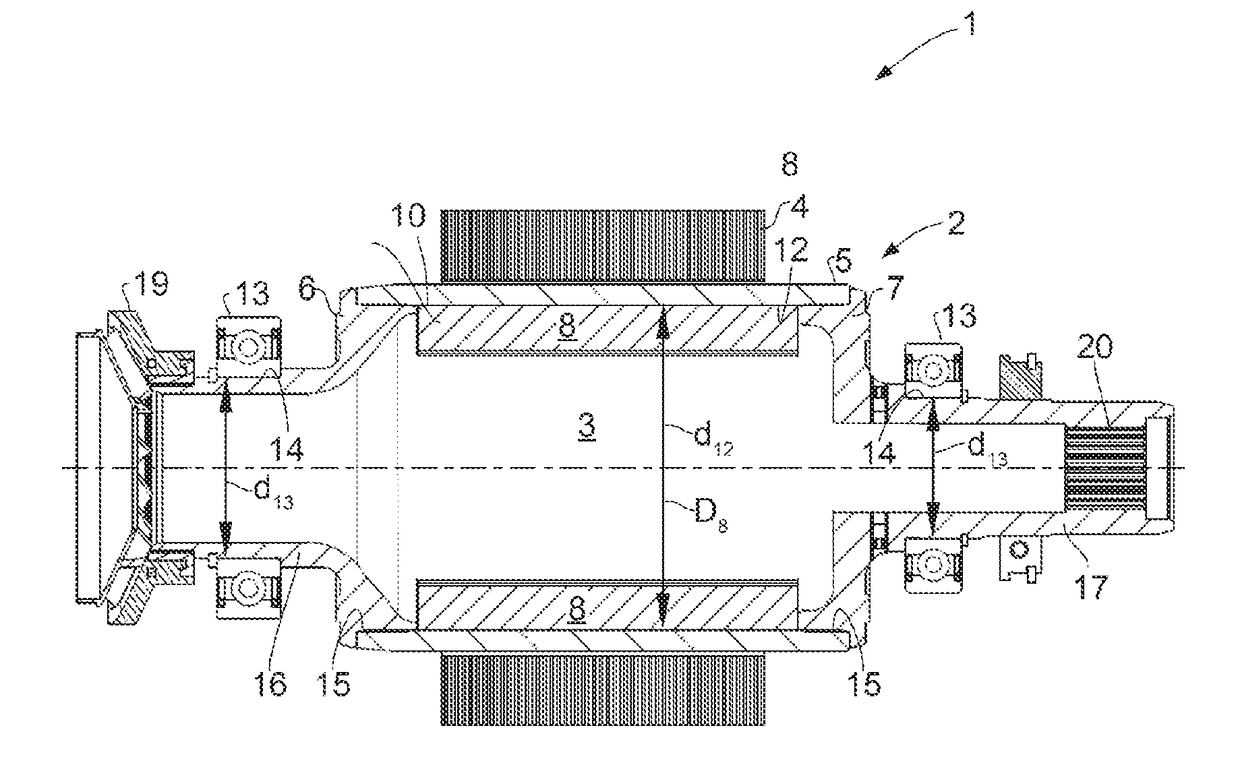
[0017]FIG. 1 shows a hollow shaft arrangement according to the invention in longitudinal section;

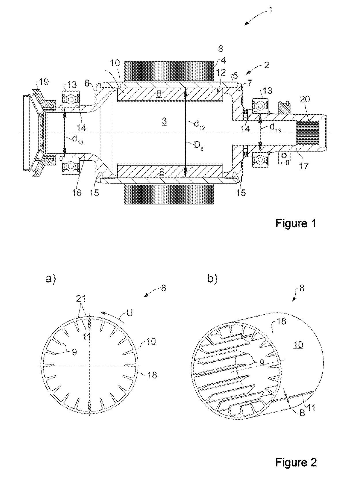
[0018]FIG. 2 shows a cooling body of the hollow shaft arrangement as per FIG. 1[0019]a) in front view;[0020]b) in a perspective illustration;

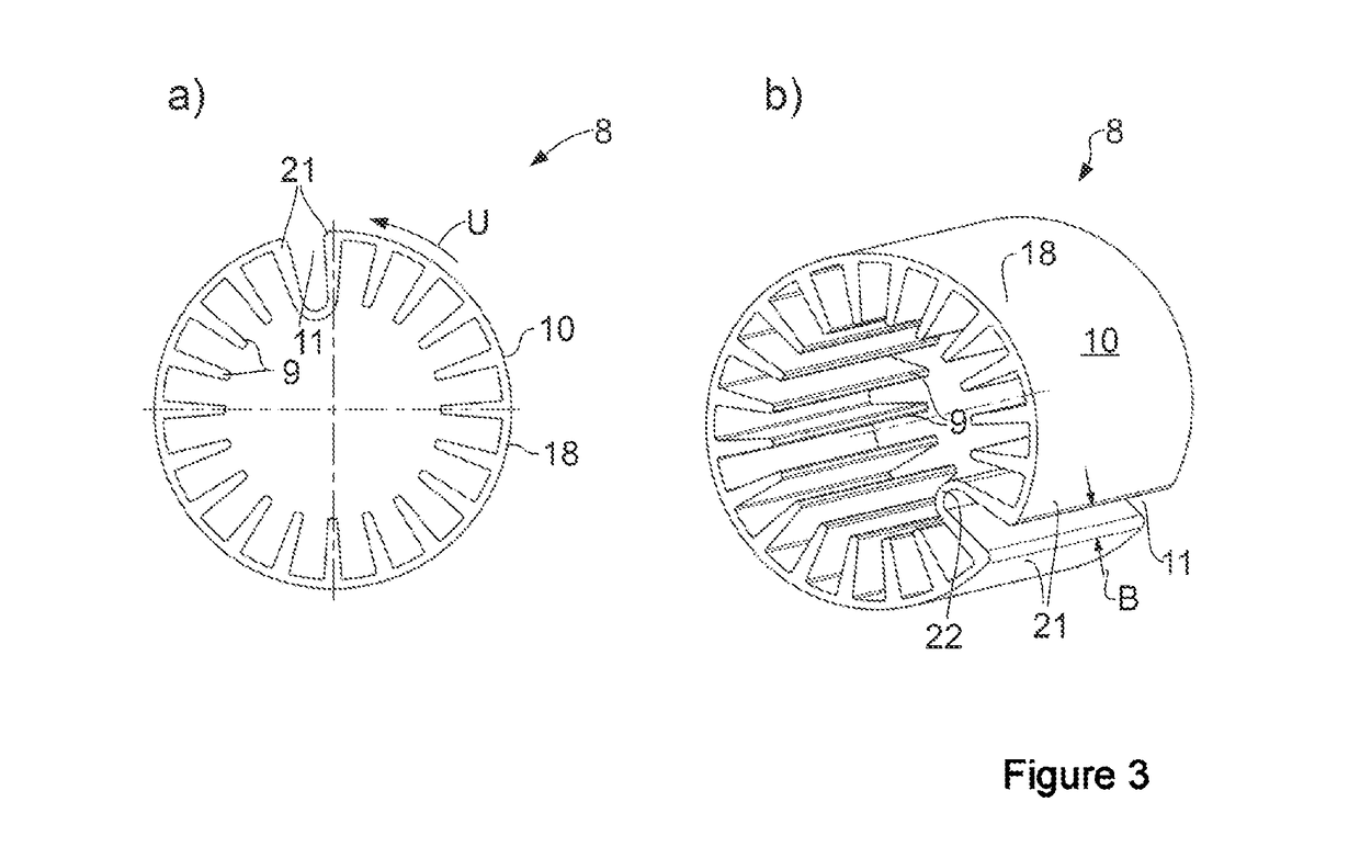
[0021]FIG. 3 shows a refinement of the cooling body of the hollow shaft arrangement as per FIG. 1[0022]a) in front view;[0023]b) in a perspective illustration.

[0024]FIG. 1 shows a hollow shaft arrangement 1 according to the invention, which may be used for example in a drivetrain of a hybrid vehicle. The hollow shaft arrangement 1 comprises a rotor shaft 2 which is in the form of a hollow shaft. A rotor of an electric motor is fastened on an outer circumference of the rotor shaft 2. The lamination pack 4 of the rotor can be seen. On one a...


PUM


Abstract

A hollow shaft arrangement may include a hollow shaft, such as a rotor shaft of an electric motor, for example, through which a fluid can pass for cooling purposes. Surface-enlarging cooling structures for transferring thermal energy from the hollow shaft to the fluid may be arranged in an inner space of the hollow shaft. The surface-enlarging cooling structures may be connected to the hollow shaft, but may be part of a cooling body that is formed separately from the hollow shaft. Further, the cooling body may include a sleeve-like main body from which the surface-enlarging cooling structures project radially inwardly, and the sleeve-like main body may include an axial gap that permits a circumference of the main body to be adjustable. In some cases an outer diameter of the cooling body is larger than an inner diameter of the bearing.

Description

[0001]The present invention relates to a hollow shaft arrangement as per the preamble of claim 1, and to a method for assembling a hollow shaft arrangement as per claim 9.PRIOR ART[0002]DE 10 2008 043 367 A1 discloses a hybrid drive device for a motor vehicle, having an internal combustion engine and an electric motor, in each case for driving the motor vehicle. A rotor of the electric motor is arranged on a hollow shaft in the drivetrain. Means for conveying a cooling fluid convey said cooling fluid through the inner space of the hollow shaft in order to cool the rotor and the hollow shaft.[0003]Cooling fins are arranged in the inner space of the hollow shaft in order to transfer the heat to the cooling fluid in the best way possible. The cooling fins are formed integrally on the inner wall of the hollow shaft in a fairly complex manner. Also, the inner diameter of the hollow shaft, and thus the diameter of the region which is able to be used for the cooling, is quite small in size...

Claims


Application Information

Patent Timeline
IPC IPC(8): B60K17/24H02K9/00H02K9/22
CPCB60K17/24H02K9/005B60K2001/006B60Y2306/05H02K9/22B60K1/00B60K17/22H02K1/32H02K9/00H02K9/227F16D2300/0214B60Y2304/07B60K6/26F16C3/02H02K5/18
Inventor MUSTER, MANFREDPAUL, DANIEL
Owner THYSSENKRUPP PRESTA TECCENTER AG
Why Eureka
Try Eureka