Connecting Device for Concealed-Type Top or Bottom Latch for Panic Exit Door Lock

a top or bottom latch, concealed technology, applied in the direction of building locks, constructions, fastening means, etc., can solve the problems of adversely affecting the operation of the latch, difficult installation for a single installer, and easy installation of surfaced type latches, etc., to facilitate the description of the invention

Active Publication Date: 2010-05-13
I TEK METAL MFG
View PDF12 Cites 16 Cited by
  • Summary
  • Abstract
  • Description
  • Claims
  • Application Information

AI Technical Summary

Benefits of technology

[0021]FIG. 12 shows a perspective view of a panic exit door and a conventional lock, illustrating mounting of a connecting device and a latch of the lock to the panic exit door.
[0022]All figures are drawn for ease of explanation of the basic teachings of the present invention only; the extensions of the figures with respect to number, position, relationship, and dimensions of the parts to form the preferred embodiment will be explained or will be within the skill of the art after the following teachings of the present invention have been read and understood. Further, the exact dimensions and dimensional proportions to conform to specific force, weight, strength, and similar requirements will

Problems solved by technology

Surfaced type latches are easy to install but can not provide an aesthetically pleasing appearance.
Such installation is difficult for a single i

Method used


Image

  • Connecting Device for Concealed-Type Top or Bottom Latch for Panic Exit Door Lock
  • Connecting Device for Concealed-Type Top or Bottom Latch for Panic Exit Door Lock
  • Connecting Device for Concealed-Type Top or Bottom Latch for Panic Exit Door Lock

Examples


Embodiment Construction

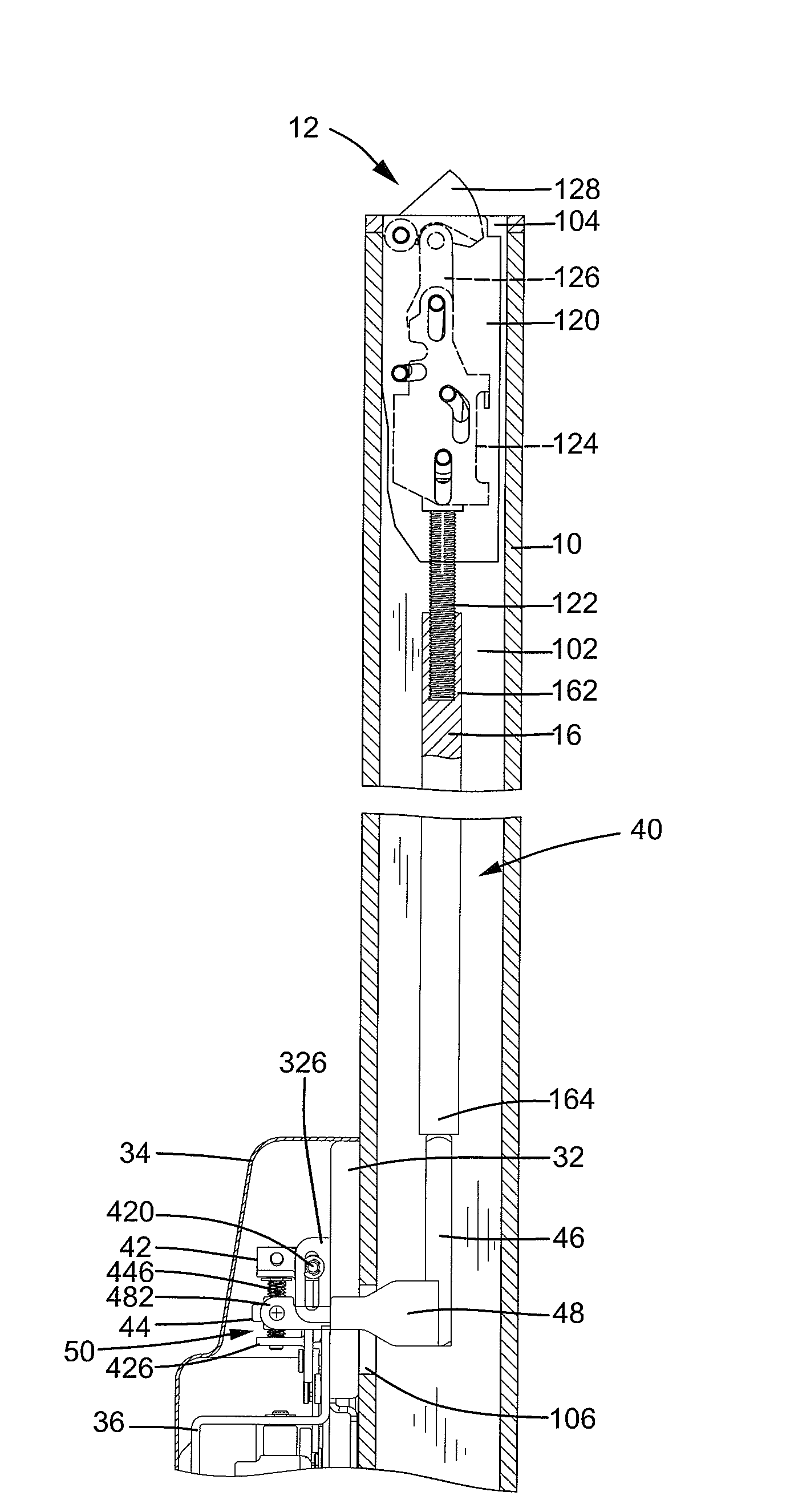
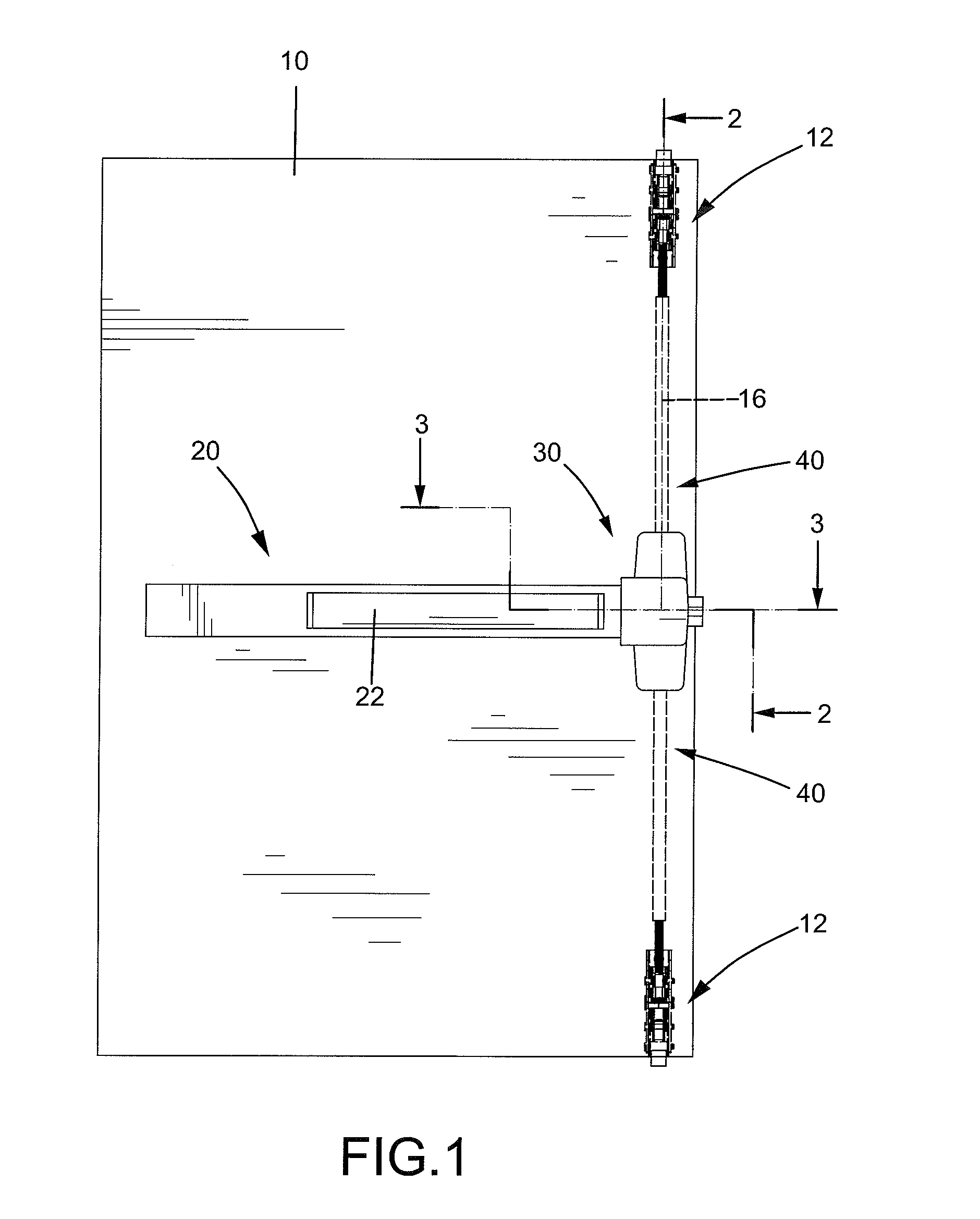
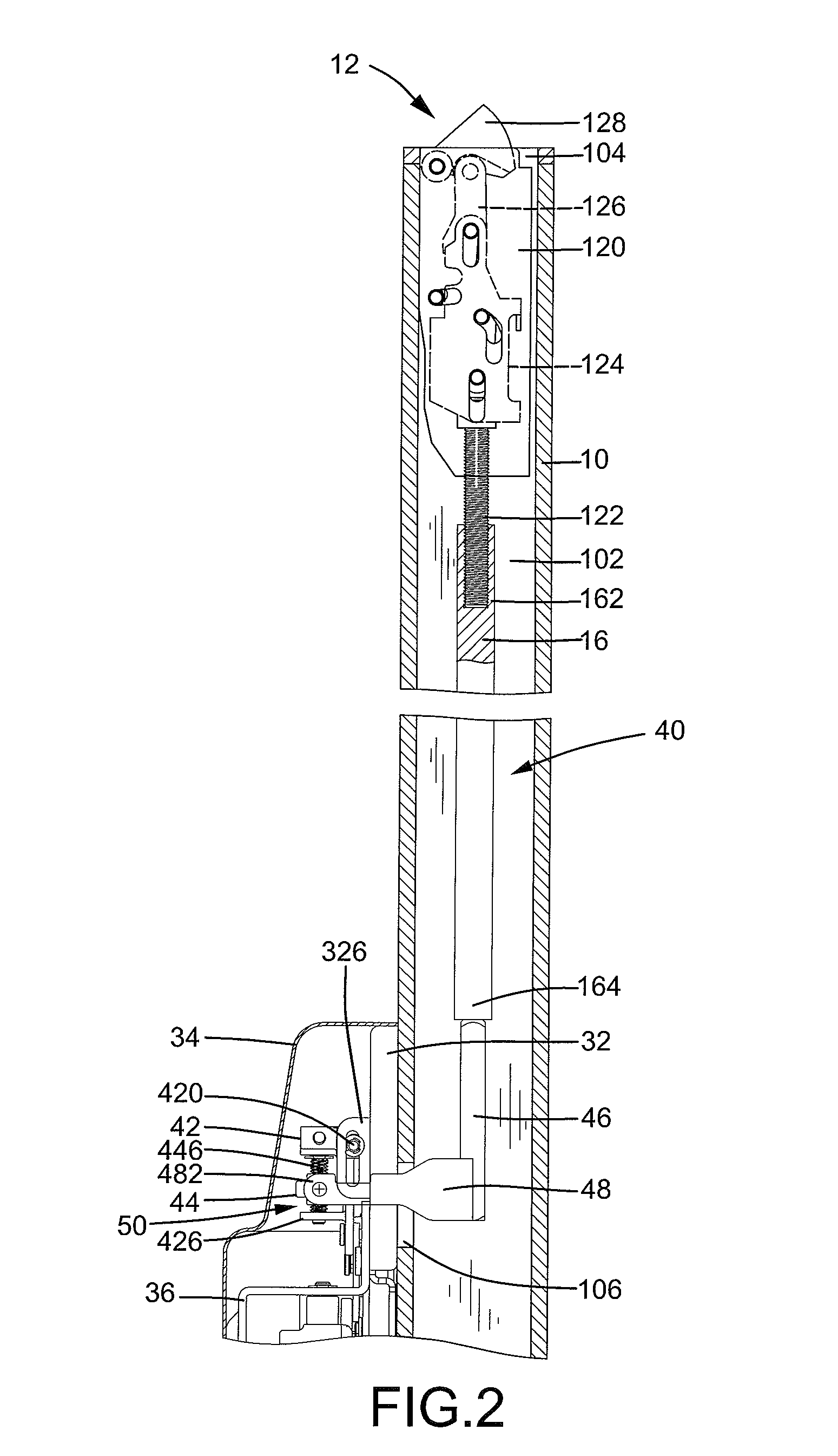
[0024]A connecting device according to the preferred teachings of the present invention is shown in the drawings and generally designated 40. Connecting device 40 is generally utilized with a panic device or lock mounted to a panic exit door 10. According to the preferred form shown, the lock mounted to door 10 includes an operative device 20, a follower device 30 operably connected to operative device 20, top and bottom latch devices 12 operably connected to follower device 30, a sliding device 50, and two connecting devices 40 according to the preferred teachings of the present invention. Operative device 20 and follower device 30 are mounted to an inner side of door 10. Door 10 is hollow and includes an interior space 102. Door 10 further includes an end opening 104 in each of a top edge and a bottom edge thereof. Door 10 further includes two side openings 106 in the inner side (see FIG. 9). End openings 104 and side openings 106 are in communication with interior space 102. Acco...


PUM


Abstract

A lock for a door includes a latch (128) to which an end of a connecting member (46) is operably coupled. A draw rod (48) is securely mounted to the connecting member (46) to move therewith. A base (32) is fixed to the door, and a slide (42) is slideably mounted to the base (32) in the vertical direction. An adjusting block (44) is fixed to the draw rod (48) to move therewith. An adjusting screw (446) is rotatably extended through the slide (42) and threadedly engaged with the adjusting block (44) so that movement of the slide (42) in the vertical direction causes movement of the adjusting block (44) and the connecting member (46) in the vertical direction and of the latch (128) between locking and unlocking positions. Rotation of the adjusting screw (446) causes movement of the adjusting block (44) and the connecting device (40) in the vertical direction to adjust the locking position of the latch (128) relative to the door (10).

Description

CROSS REFERENCE TO RELATED APPLICATION[0001]This is a continuation-in-part application of U.S. patent application Ser. No. 12 / 211,879 filed Sep. 17, 2008.BACKGROUND OF THE INVENTION[0002]The present invention relates to a connecting device for a panic exit door lock and, more particularly, to a connecting device for a concealed-type top or bottom latch for a panic exit door lock that allows easy mounting of the connecting device and that allows adjustment of projection of the top or bottom latch beyond a top face or a bottom face of the panic exit door to allow easy mounting of the lock.[0003]Locks for panic exit doors include horizontal type latches and vertical type latches. Vertical type latches include a top latch and a bottom latch, wherein the top and bottom latches include concealed type and surfaced type according to the way they are mounted. Surfaced type latches are easy to install but can not provide an aesthetically pleasing appearance. Concealed type latches provide an ...

Claims


Application Information

Patent Timeline
IPC IPC(8): E05B65/10
CPCE05B65/1006E05B63/0056Y10T292/0822Y10T292/0908
Inventor SHEN, CHUN-MENG
Owner I TEK METAL MFG
Why Eureka
Try Eureka