Operational Device for Lock

a technology of operation device and lock, which is applied in the direction of keyhole guards, wing knobs, furniture parts, etc., can solve the problems of weakening of the structural strength of the spring seat and difficulties in lock design, and achieve the effect of facilitating the description of the invention

Inactive Publication Date: 2010-11-04
I TEK METAL MFG
View PDF11 Cites 6 Cited by
  • Summary
  • Abstract
  • Description
  • Claims
  • Application Information

AI Technical Summary

Benefits of technology

[0019]All figures are drawn for ease of explanation of the basic teachings of the present invention only; the extensions of the figures with respect to number, position, relationship, and dimensions of the parts to form the preferred embodiments will be explained or will be within the skill of the art after the following teachings of the present invention have been read and understood. Further, the exact dimensions and dimensional proportions to conform to specific force, weight, strength, and similar requirements will likewise be within the skill of the art after the following teachings of the present invention have been read and understood.
[0020]Where used in the various figures of the drawings, the same numerals designate the same or similar parts. Furthermore, when the terms “first”, “second”, “inner”, “outer”, “side”, “end”, “portion”, “section”, “axial”, “radial”, “circumferential”, “lateral”, “horizontal”, “annular”, “outward”, and similar terms are used herein, it should be understood that these terms have reference only to the structure shown in the drawings as it would appear to a person viewing the drawings and are utilized only to facilitate describing the invention.

Problems solved by technology

The wings and the lug are formed by bending a strip that forms each spring device such that the spring device includes a plurality of holes, leading to weakening of the structural strength of the spring seat.
Furthermore, the engaging piece protrudes from an outer periphery of the sleeve in a specific orientation such that the inner or outer handle can only be coupled to the sleeve in a single orientation.
Similarly, each spring device must include four corresponding holes, leading to difficulties in lock designing.

Method used


Image

  • Operational Device for Lock
  • Operational Device for Lock
  • Operational Device for Lock

Examples


Embodiment Construction

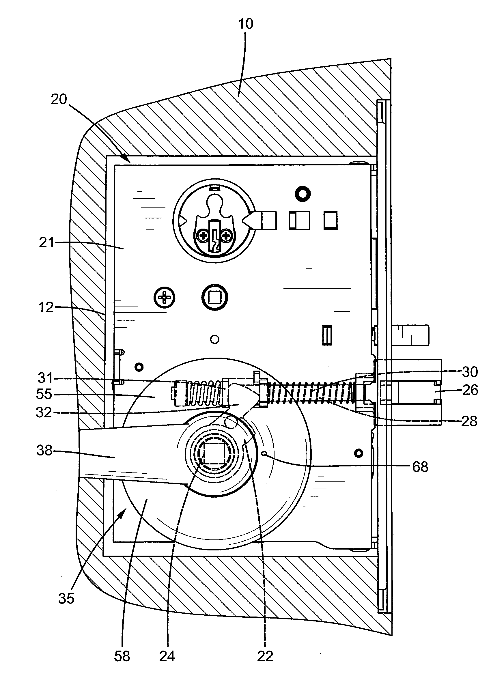
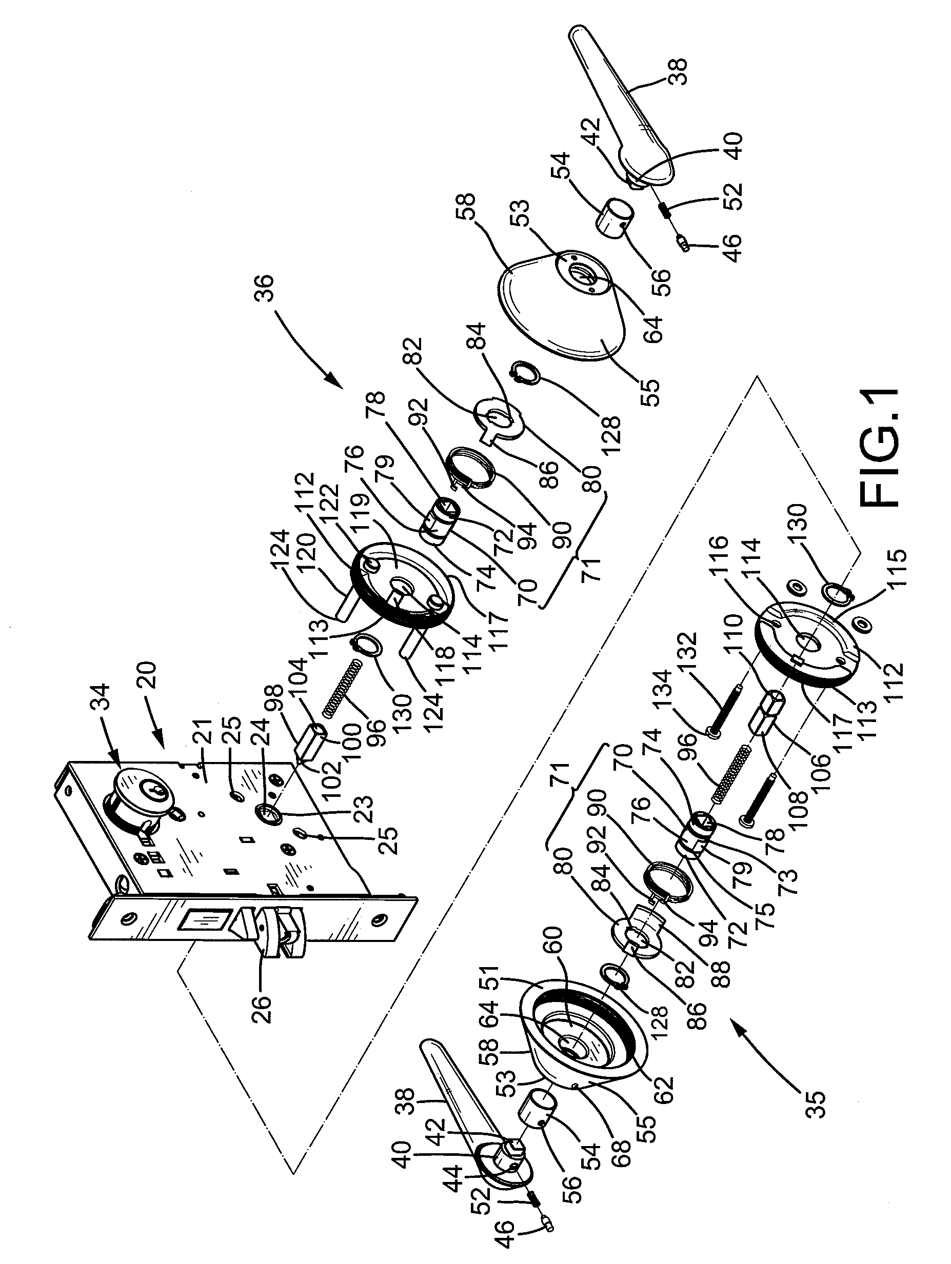
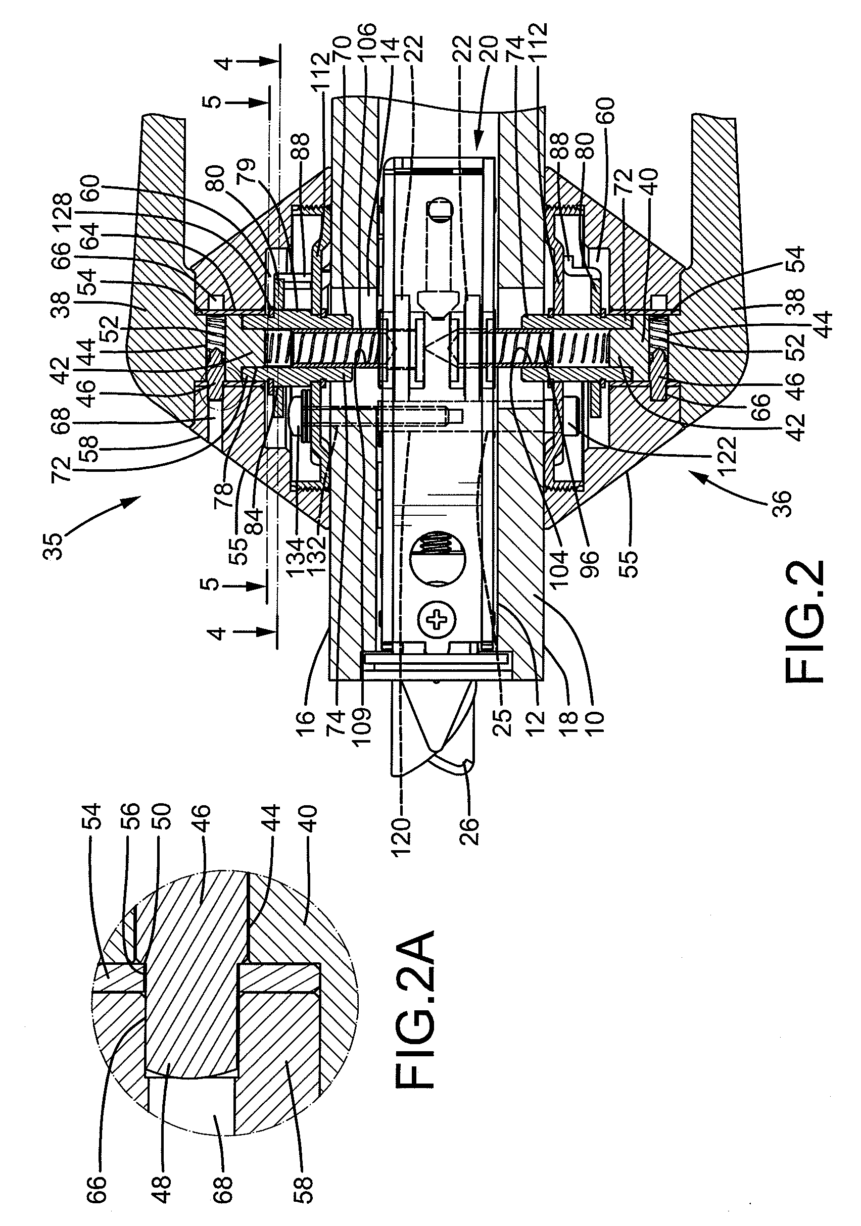
[0021]A lock according to the preferred teachings of the present invention is shown in the drawings and generally designated 20. Lock 20 is mounted to a door 10 having inner and outer sides 16 and 18 and a compartment 12 intermediate inner and outer sides 16 and 18. Each of inner and outer sides 16 and 18 includes an opening 14 in communication with compartment 12. Openings 14 are aligned with each other. Each of inner and outer sides 16 and 18 further includes two diametrically opposed installing holes spaced from opening 14 in a diametric direction. According to the preferred form shown, lock 20 includes a case 21 received in compartment 12 of door 10. Case 21 includes inner and outer lateral sides each having a hole 23 aligned with one of openings 14 and each having two mounting holes 25 diametrically arranged outside of hole 23. Mounting holes 25 are aligned with the installing holes of inner and outer sides 16 and 18 of door 10. Lock 20 further includes a key-operable cylinder ...


PUM


Abstract

A lock (20) includes an operational device (35) having a disc (112) mounted to an inner side (16) of a door (10). A sleeve (70) is rotatably received in the disc (112) and includes an axial hole (78) having non-circular cross sections that are not changed after rotating 180°. A linking rod (106) includes an inner end (110) engaged in a hole (24) of a drive member (22) in a case (21) mounted in the door (10). A cover (58) is mounted around the disc (112) and includes a pivot hole (64). A handle (38) includes a pivotal portion (40) and a drive portion (42) formed on an end face of the pivotal portion (40). The drive portion (42) has cross sections the same as the axial hole (78) of the sleeve (70). The pivotal portion is (40) pivotably received in the pivot hole (64) of the cover (58). The drive portion (42) is engaged in the axial hole (78) of the sleeve (70).

Description

BACKGROUND OF THE INVENTION[0001]The present invention relates to an operational device for a lock and, more particularly, to an operational device for a lock to control opening and closing of a door to which the lock is mounted.[0002]A wide variety of door locks is available in the market. In a type of the door locks, a latch of the lock is movably received in a case and can be retracted by an operational device outside of the case to provide versatile applications while enhancing security. In an example, the lock includes inner and outer handles coupled to inner and outer spindles. A spring device is attached to each of the inner and outer handles for returning the inner and outer handles. Each spring device includes a sleeve having an engaging piece. Each of the inner and outer handles is coupled to the sleeve of one of the spring devices and positioned by the engaging piece. Furthermore, each spring device includes a spring seat having a plurality of wings and a lug for limiting...

Claims


Application Information

Patent Timeline
Patent Type & Authority Applications(United States)
IPC IPC(8): E05B65/00E05B7/00
CPCE05B3/065E05B13/005Y10T16/44E05B63/04E05B63/0065Y10T70/5155
Inventor LIN, CHUNG-LIANG
Owner I TEK METAL MFG
Why Eureka
Try Eureka