Universal Joint with Wider Working Angle Range

a working angle and universal joint technology, applied in the field of universal joints, can solve the problems of disengagement of the yoke member, inability to work through manual operation, and inability to achieve high-speed operation with a power tool, etc., to facilitate the description of the invention

Inactive Publication Date: 2009-01-22
HU BOBBY
View PDF1 Cites 8 Cited by
  • Summary
  • Abstract
  • Description
  • Claims
  • Application Information

AI Technical Summary

Benefits of technology

[0017]All figures are drawn for ease of explanation of the basic teachings of the present invention only; the extensions of the Figures with respect to number, position, relationship, and dimensions of the parts to form the preferred embodiment will be explained or will be within the skill of the art after the following teachings of the present invention have been read and understood. Further, the exact dimensions and dimensional proportions to conform to specific force, weight, strength, and similar requirements will likewise be within the skill of the art after the following teachings of the present invention have been read and understood.
[0018]Where used in the various figures of the drawings, the same numerals designate the same or similar parts. Furthermore, when the terms “first”, “second”, “end”, “section”, “periphery”, “centrifugal”, “lateral”, and similar terms are used herein, it should be understood that these terms have reference only to the structure shown in the drawings as it would appear to a person viewing the drawings and are utilized only to facilitate describing the invention.

Problems solved by technology

As a result, this universal joint 90 can only work through manual operation; i.e., this universal joint 90 is not suitable for high speed operation with a power tool.
However, the second pins 84 are liable to fall from the coupler 81 after a period of time due to high centrifugal force resulting from high speed rotation, leading to disengagement of the yoke member 85.

Method used


Image

  • Universal Joint with Wider Working Angle Range
  • Universal Joint with Wider Working Angle Range
  • Universal Joint with Wider Working Angle Range

Examples


Embodiment Construction

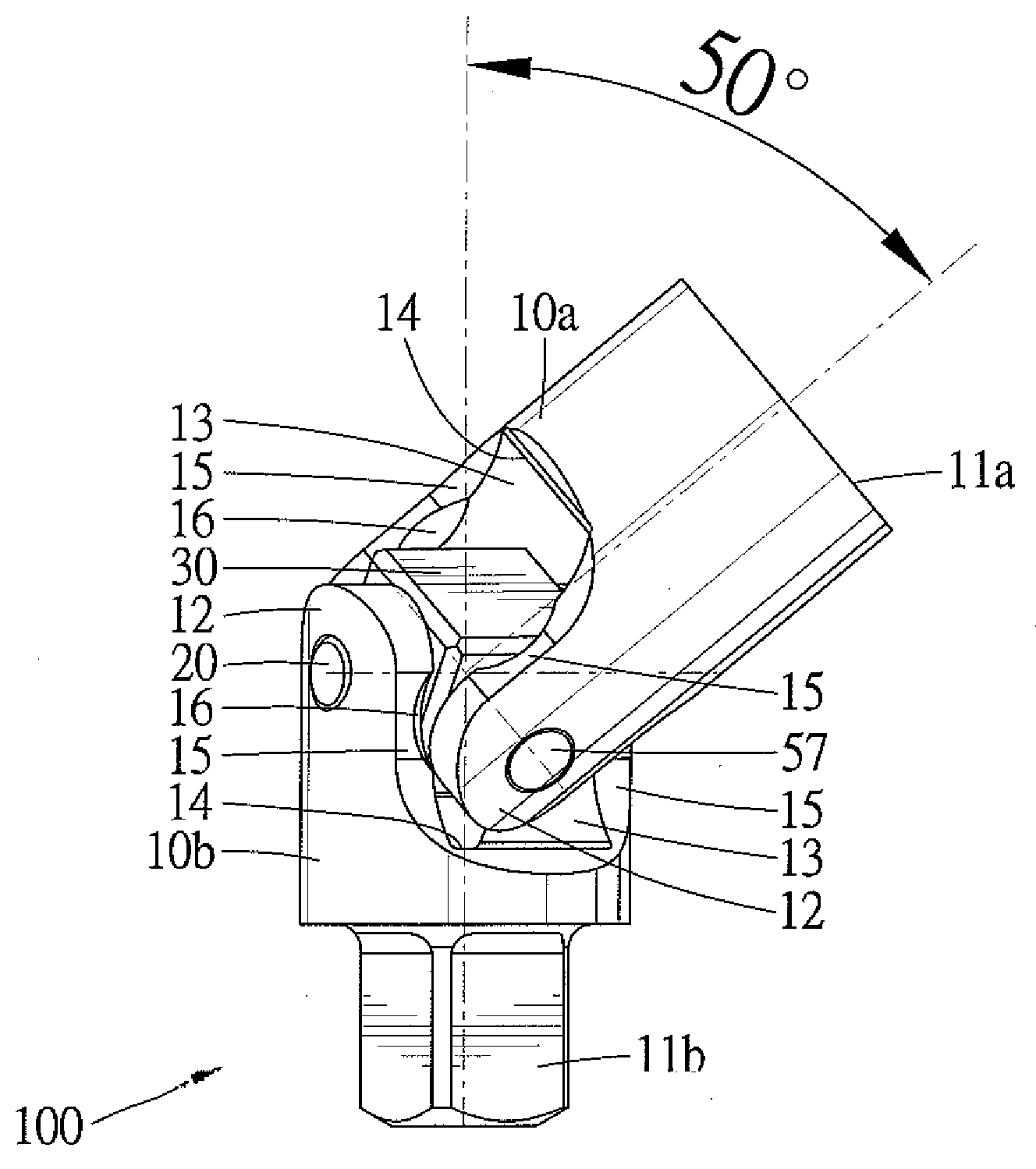
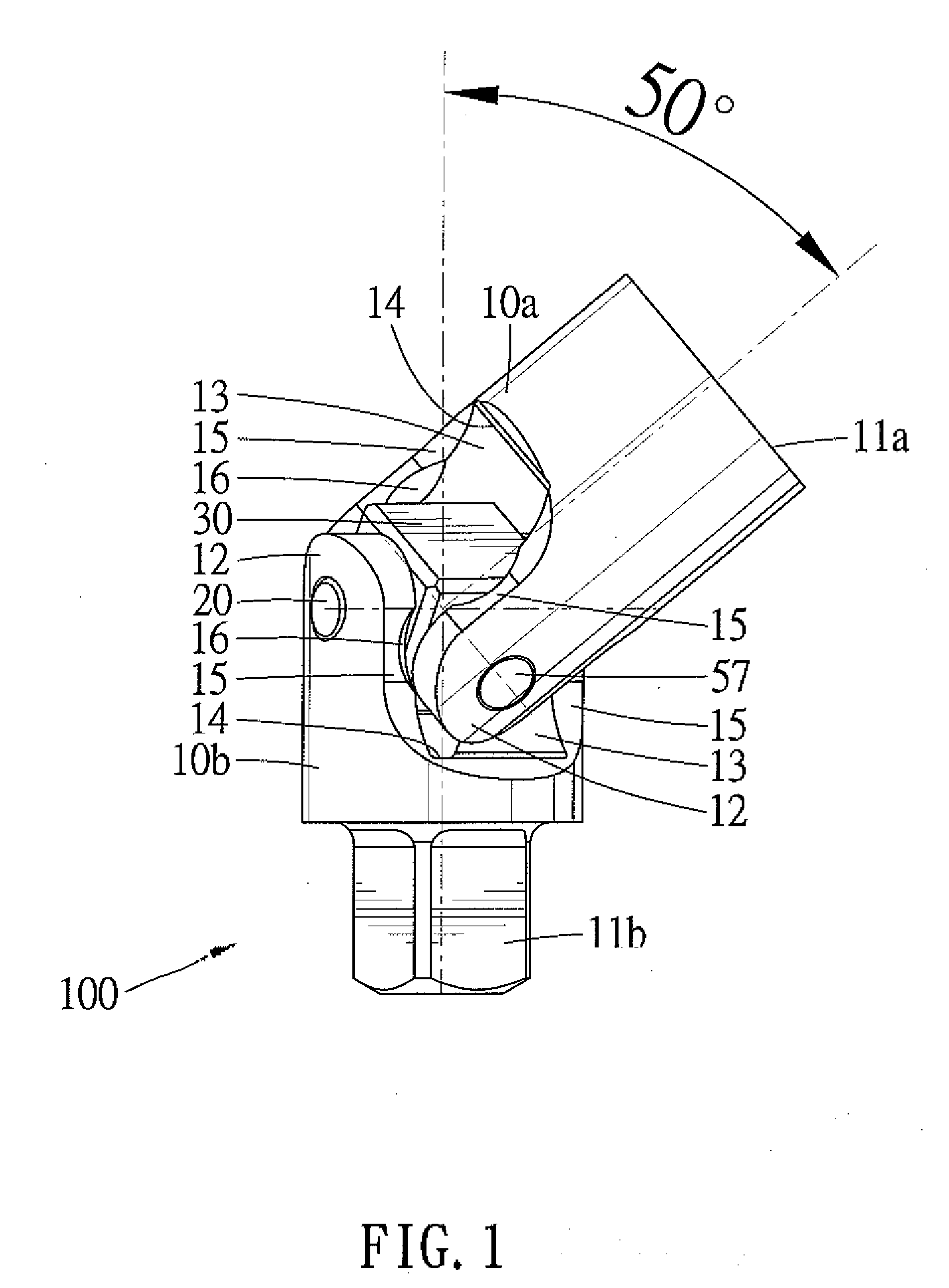
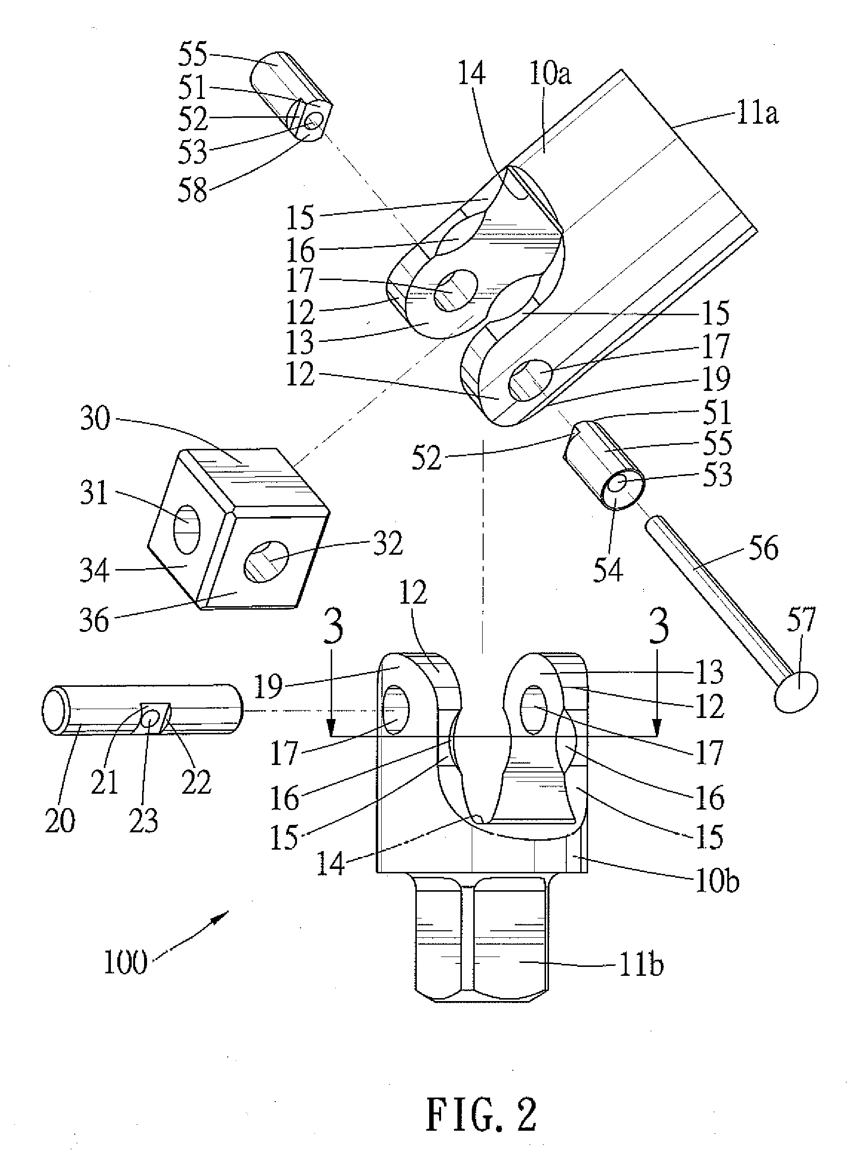
[0019]A universal joint according to the preferred teachings of the present invention is shown in FIGS. 1-5 of the drawings and designated 100. The universal joint 100 includes a pair of yoke members 10a and 10b. In the preferred form shown, the yoke member 10a includes a coupling end 19 and a power input end 11a in the form of a socket for coupling with a power tool for high speed operations. Other forms of the power input end 11a would be within the skill of the art. The yoke member 10b includes a coupling end 19 and a power output end 11b in the form of a drive column for coupling with a socket. Other forms of the power output end 11b would be within the skill of the art. In the most preferred form shown, the coupling ends 19 of the yoke members 10a and 10b are identical. Thus, description of one of the coupling ends 19 would be sufficient.

[0020]In the most preferred form shown, the coupling end 19 includes a pair of spaced arms 12 having aligned pivot holes 17 and mutually facin...


PUM


Abstract

A universal joint includes a pair of yoke members each having a pair of spaced arms. A coupler is pivotably coupled with the arms of the yoke members to allow the yoke members to respectively pivot about two pivot axes perpendicular to each other. Each arm includes two mutually facing inner faces and an intermediate face interconnected between the inner faces. Each arm further includes a pair of opposite lateral sides between which one of the inner faces extends. A recess is formed between each lateral side of each arm and one of the inner faces of one of the arms. The recesses of the arms of one of the yoke members allow entrance of the arms of the other yoke member.

Description

BACKGROUND OF THE INVENTION[0001]The present invention relates to a universal joint and, more particularly, to a universal joint with a larger working angle range.[0002]Various universal joints exist for providing power transmission from a power source to a member to be driven. FIGS. 6 and 7 show a conventional universal joint 90 including a pair of yoke members 93 and 95 and a coupler 91. The yoke member 95 includes a power input end 96, and the other yoke member 93 includes a power output end 97 for coupling with a socket. The coupler 91 includes a first through-hole 98 extending through a pair of opposite faces thereof and a second through-hole 99 extending through another pair of opposite faces thereof and orthogonal to but spaced from the first through-hole 98. The coupler 91 is pivotably coupled with the yoke member 93 by a first pin 92 extending through aligned pin holes 930 of the yoke member 93 and the first through-hole 98 of the coupler 91. Furthermore, the coupler 91 is ...

Claims


Application Information

Patent Timeline
Patent Type & Authority Applications(United States)
IPC IPC(8): F16D3/26
CPCF16D3/385
Inventor HU, BOBBY
Owner HU BOBBY
Why Eureka
Try Eureka