Rod Assembly Connector for Mounting Light Emitting Display Apparatuses

a technology for mounting connectors and light emitting display devices, which is applied in the direction of rod connections, identification means, instruments, etc., can solve the problems of large display panels that may be large and heavy, have limitations on transparency and weight, and may have the traditional fixed structure of led video panels

Inactive Publication Date: 2010-06-03
BARCO INC
View PDF12 Cites 15 Cited by
  • Summary
  • Abstract
  • Description
  • Claims
  • Application Information

AI Technical Summary

Problems solved by technology

As the LED video market expands into new domains, the classic fixed structure of the LED video panel may become a limitation.
For example, a panel or modular box system may work well in a stadium score board or as an advertisement on the Las Vegas Strip, but the large panels may have limitations on transparency and weight.
A display apparatus constructed as a large panel or as a series of solid tiles bolted or permanently fixed together may be very inappropriate for such an application or need.
The displays may be large and heavy, and require abundant support machinery, time, and storage space for installation.
However, there may be limitations to the method disclosed in Tokimoto.
For example, maintaining the system within the void is complicated.
The system disclosed by Tokimoto could be used to back light a graphic on the glass exterior; however, issues with line of sight would prevent the system from acting as a part of the graphic.
This may be the result in the alignment of the system and the graphic shifting as the viewer moves.
Further, the system may not function as a finished surface and may be difficult to access and maintain.
However, while these LED tile systems usually focus on transparency and light weight, the systems generally require frames and ground support structures.
As such, these systems generally create an additional cost and tend to work against the goal of creating a transparent and light weight wall system.

Method used


Image

  • Rod Assembly Connector for Mounting Light Emitting Display Apparatuses
  • Rod Assembly Connector for Mounting Light Emitting Display Apparatuses
  • Rod Assembly Connector for Mounting Light Emitting Display Apparatuses

Examples


Embodiment Construction

[0021]Specific embodiments of the present disclosure will now be described in detail with reference to the accompanying figures. Like elements in the various figures may be denoted by like reference numerals for consistency. Further, in the following detailed description of embodiments of the present disclosure, numerous specific details are set forth in order to provide a more thorough understanding of the invention. However, it will be apparent to one of ordinary skill in the art that the present invention may be practiced without these specific details. In other instances, well-known features have not been described in detail to avoid unnecessarily complicating the description.

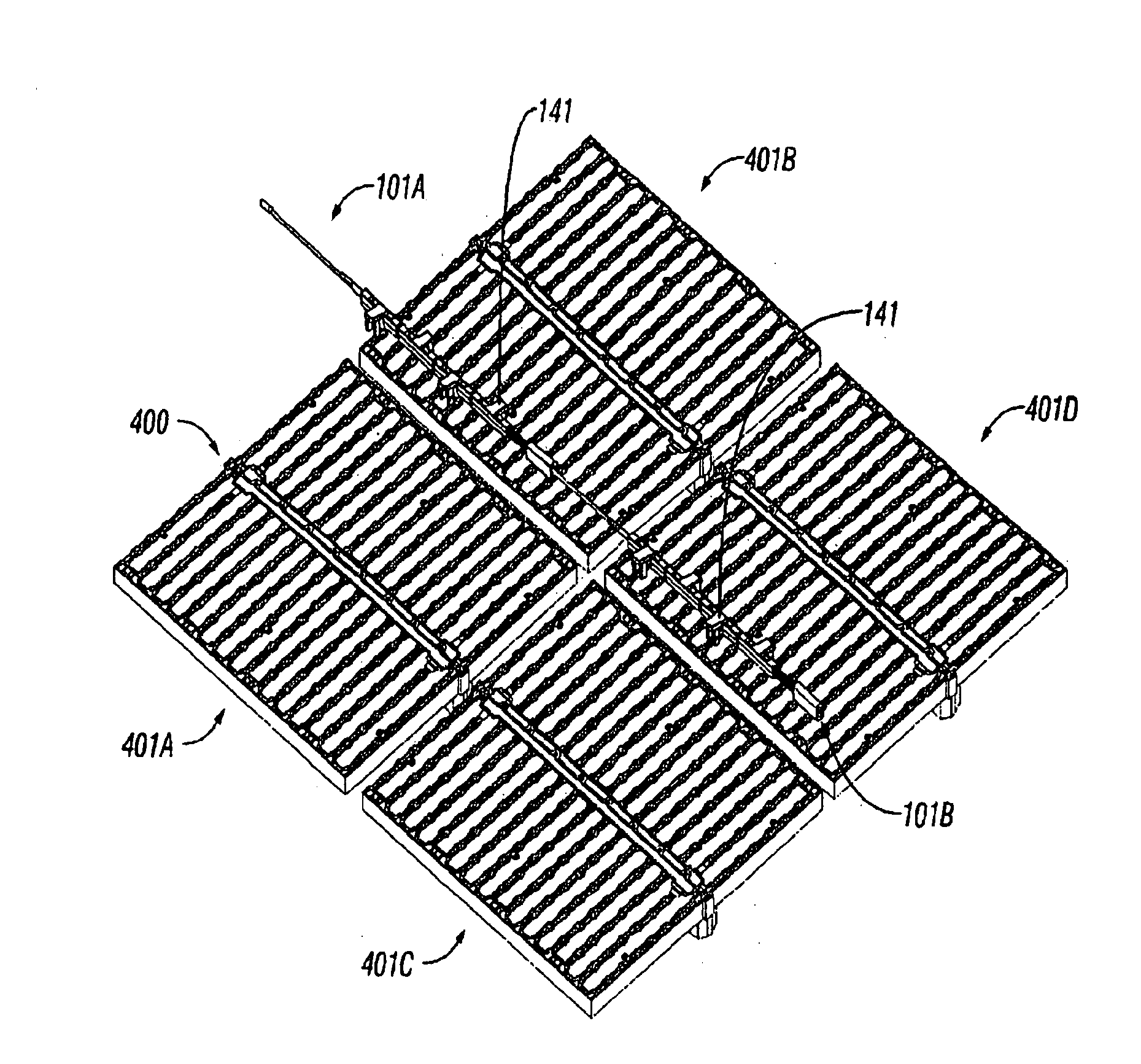
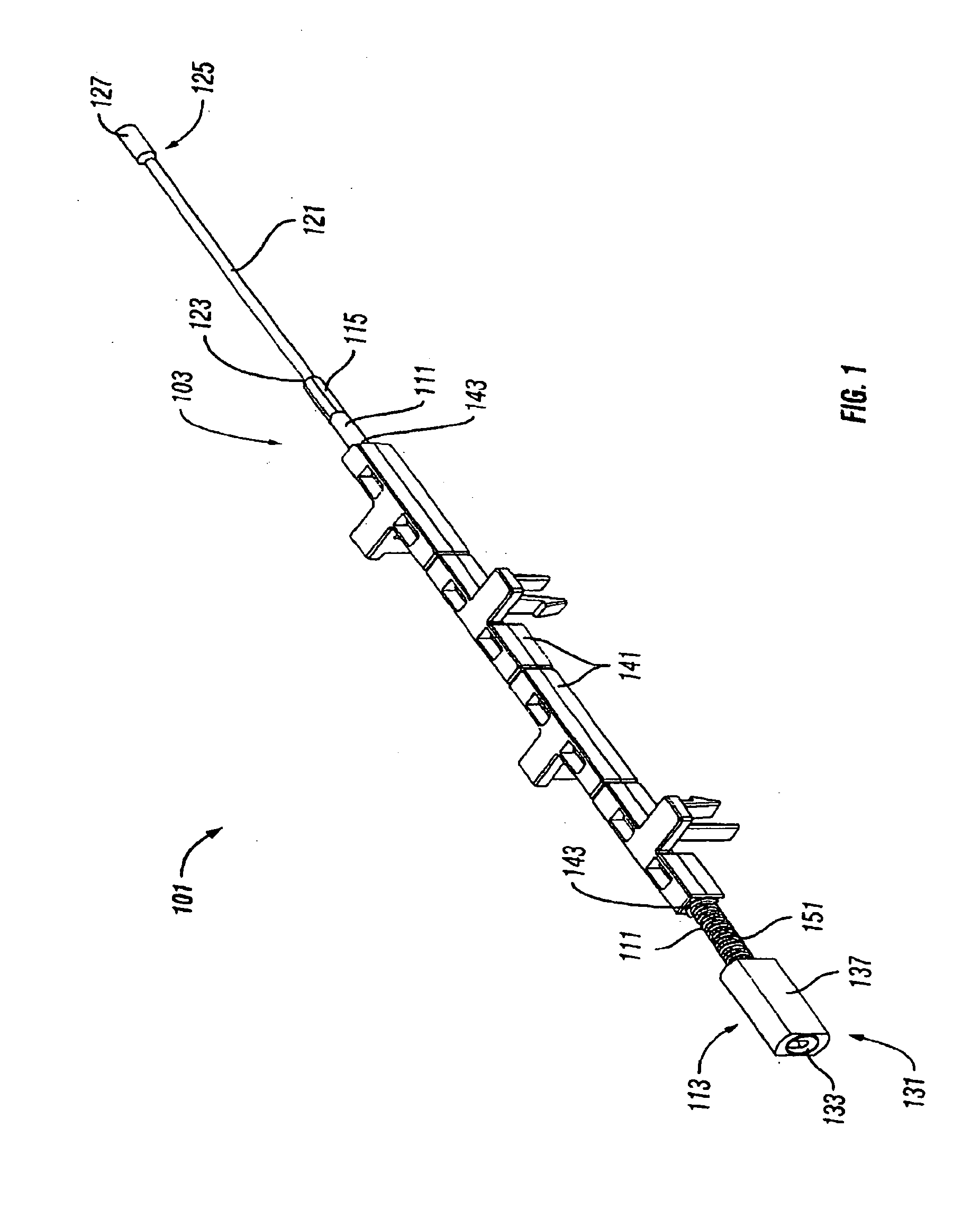
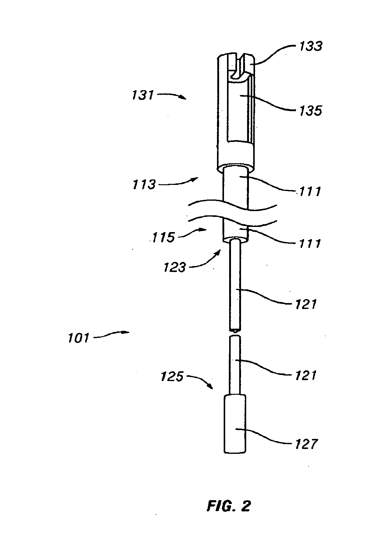
[0022]In one aspect, embodiments disclosed herein generally relate to a rod assembly connector for supporting and mounting light emitting display apparatuses and systems. The rod assembly connector includes a coupler at one end, in which multiple rod assembly connectors may be connected by attaching the end...


PUM


Abstract

A method and system for connecting a light emitting apparatus is disclosed herein. The system includes at least two rod assembly connectors, in which each rod assembly connector includes a rod assembly body having a first end and a second end. The first end of one of the rod assembly connectors is configured to connect with the second end of the second rod assembly connector. Further, at least one of the rod assembly connectors includes an attachment mechanism, in which the attachment mechanism is configured to attach to a light emitting apparatus.

Description

CROSS-REFERENCE TO RELATED APPLICATIONS[0001]This application, pursuant to 35 U.S.C. § 119(e), claims priority to U.S. Patent Application Ser. No. 60 / 884,859 filed on Jan. 12, 2007 and entitled “Method for Mounting Light Emitting Panels on Tensioned Cable Systems” in the name of Douglas Franklin, Christopher Varrin, Matthew Ward, Jeremy Hochman, and Jeff Maddox, which is hereby incorporated by reference in its entirety.BACKGROUND[0002]1. Field of the Disclosure[0003]Embodiments disclosed herein generally relate to light emitting apparatuses and light emitting systems. More specifically, embodiments disclosed herein relate to an improved method and apparatus for mounting light emitting apparatuses and light emitting systems, particularly in which weight and transparency are a concern.[0004]2. Background Art[0005]Display units for entertainment, architectural, and advertising purposes have commonly been constructed from numbers of light emitting elements, such as light emitting diodes...

Claims


Application Information

Patent Timeline
Patent Type & Authority Applications(United States)
IPC IPC(8): F21V19/00H01J9/24F16B7/00
CPCH01R4/38H01R4/56Y10T403/57G09F9/3026H01R11/28
Inventor FRANKLIN, DOUGLASVARRIN, CHRISTOPHERWARD, MATTHEWHOCHMAN, JEREMYMADDOX, JEFFREY T.
Owner BARCO INC
Why Eureka
Try Eureka