Method for operating a resonance measuring system and a resonance measuring system

a resonance measuring system and resonance technology, applied in the direction of liquid/fluent solid measurement, direct mass flowmeter, reradiation, etc., can solve the problem of not holding true for multi-phase flow, considerable measuring errors, and rapid attenuation at occurrence and cessation

Active Publication Date: 2010-06-10
KROHNE MESSTECHNICK GMBH & CO KG
View PDF5 Cites 18 Cited by
  • Summary
  • Abstract
  • Description
  • Claims
  • Application Information

AI Technical Summary

Benefits of technology

[0014]The object of the present invention is to avoid the identified disadvantages—at least partially—in the known method for operating resonance measuring systems, in particular, to provide such a method that makes possible a quick adjustment and correction of the resonance measuring system at the—time-variant—resonance working point.
[0016]According to the invention, in determining the eigenfrequency in resonance measuring systems and in adjusting and correcting the possible time-variant working point, it is provided to simultaneously use two information sources in the determination of the eigenfrequency of the resonance measuring system in the respective eigenform, wherein an important advantage is based on the fact that both used information sources have different speeds and can be determined exactly in different excitation states of the resonance measuring system. The simultaneous determination of two values for the eigenfrequency in different ways allows for a safer, quicker and more exact determination of the eigenfrequency compared to using just one method alone. It is easily possible to obtain different parts of the response signal yi(t) by projecting the response signal onto an orthogonal frame of reference, as is known, for example, from communications engineering in the generation and analysis of quadrature components. The determined values of the eigenfrequencies can then be used in an arbitrary control for exciting the resonance measuring system at the eigenform of interest.
[0055]With a suitable choice of time difference according to the following inequalityt1-t2<πω0i-ωi,leaps in the phase calculation can be avoided.
[0062]In a further preferred embodiment of the invention, the amplitude of the oscillation of the oscillation element of the resonance measuring system is controlled at a predetermined value by a third control loop, so that ample excitation of the resonance measuring system is always guaranteed and the amplitude can simultaneously be safely limited.

Problems solved by technology

However, this does not hold true for multi-phase flows.
In using multi-phase flows, considerable measuring errors occur.
The essential cause, there, is the occurrence of an asymmetrical filling of the measuring tube during flow, which leads to a rapid fluctuation of the resonance frequency, as well as the occurrence and cessation of secondary flows in the measuring tube, which cause a quick attenuation at occurrence and a swift disattenuation at cessation.
A loss of the working point occurs in current, relatively slow—based on the speed of the instationariness of the flow—operating and controlling modes due to quick attenuation and disattenuation of the measuring tube as a result of an instationary flow and a simultaneously rapid change of the resonance frequency.
Then, the maximum available output is often not enough to maintain the oscillations of the measuring tube.
The result is that no Coriolis forces can be induced, whereby the measurability of the mass flow is lost.
Above all, the positioning of the working point in resonance measuring systems having poorly damped eigenforms is problematic as, e.g., in many Coriolis mass flowmeters, in which a resonance increase of the measuring tube oscillation can exist that is higher than a magnitude of three.
The loss of the working point is associated with a restart—partly time-consuming and energy demanding—of a resonance measuring system.
Furthermore, the loss of the working point results in that the process variables of interest related to the eigenfrequency are no longer known, so that, here, another abrupt loss of information exists.

Method used


Image

  • Method for operating a resonance measuring system and a resonance measuring system
  • Method for operating a resonance measuring system and a resonance measuring system
  • Method for operating a resonance measuring system and a resonance measuring system

Examples


Embodiment Construction

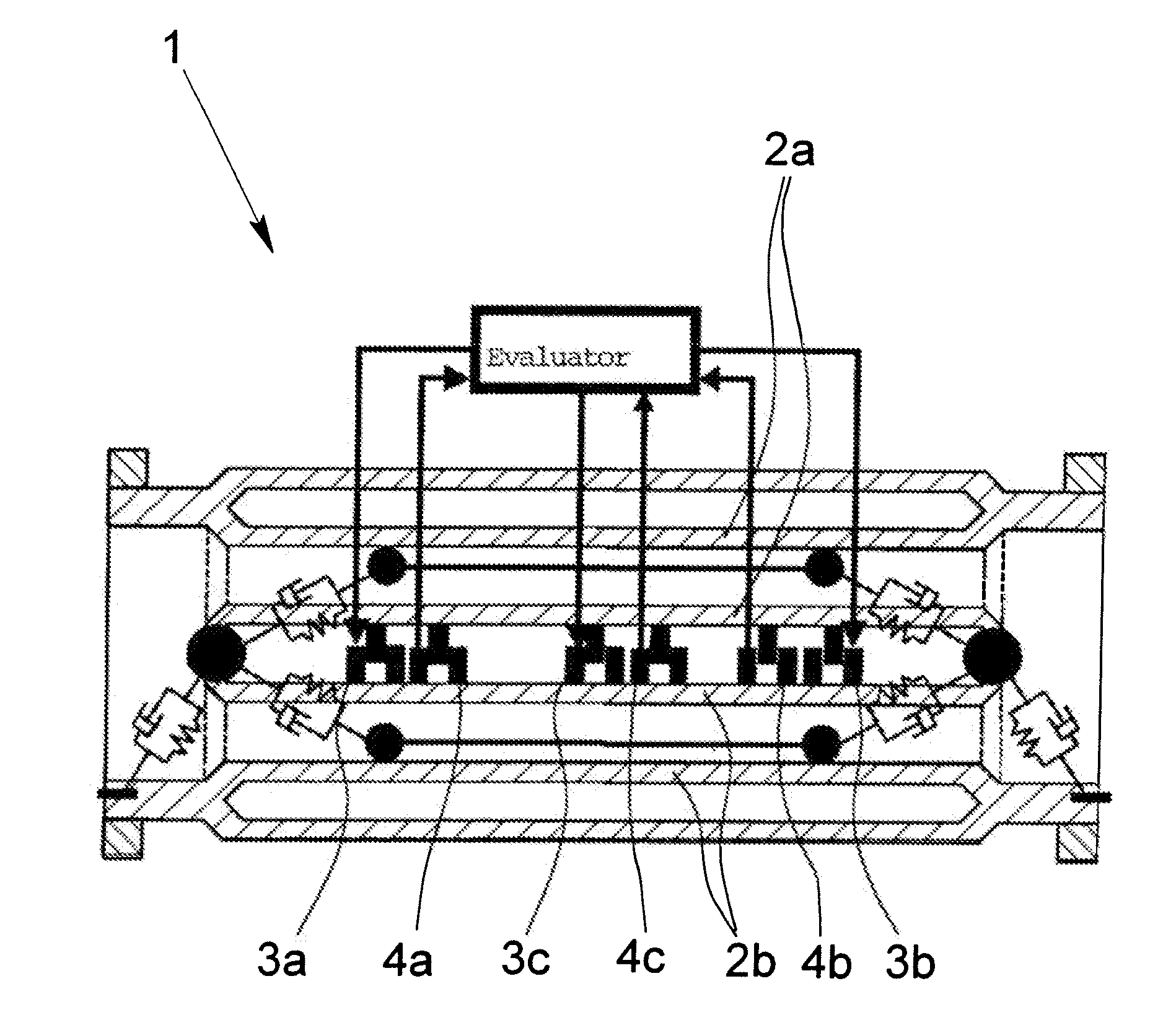
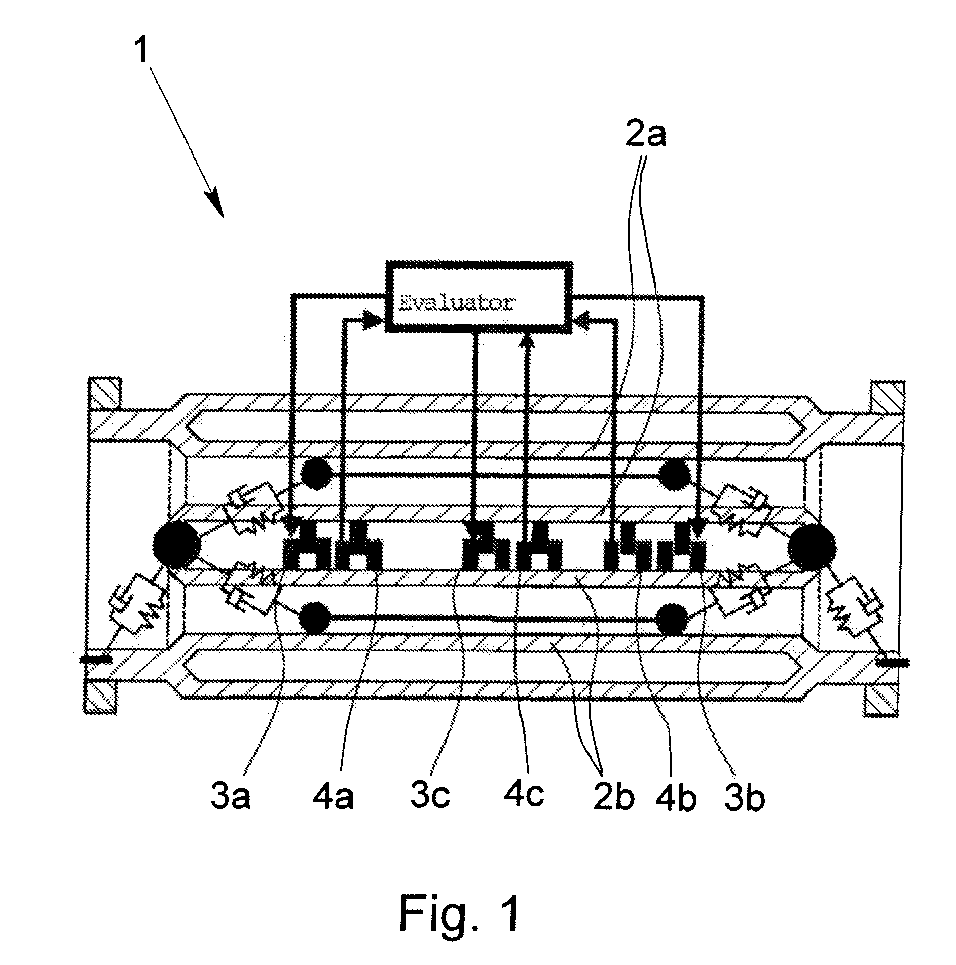
[0069]FIG. 1 shows the schematic depiction of a Coriolis mass flowmeter that is representative here for the resonance measuring system 1 in question. At hand, the resonance measuring system 1 has two interactive oscillation elements 2a, 2b, three oscillation drivers 3a, 3b, 3c and three oscillation sensors 4a, 4b, 4c. The oscillation elements 2a, 2b are excited to oscillation in at least one eigenform by the oscillation driver 3a, 3b, 3c, normally with known excitation signals Fi(t), wherein, in the case of oscillation elements 2a, 2b formed as Coriolis measuring tubes, a first eigenform can exist in an oscillation of the Coriolis measuring tubes that forms only one anti-node and a second eigenform in the oscillation of the Coriolis measuring tubes can exist in which additionally a central node of the oscillation is formed. The number of oscillation drivers 3a, 3b, 3c and oscillation sensors 4a, 4b, 4c is, in general, solely dependent on which eigenform the oscillation of the Coriol...


PUM


Abstract

A method for operating a resonance measuring system, in particular a Coriolis mass flowmeter, an oscillation element is excited to oscillation and the oscillations of the oscillation element are detected by an oscillation sensor and are formed as at least one response signal of a respective eigenform. Orthogonal projection components of the response signal are created, at least a first value corresponding to an eigenfrequency of the resonance measuring system is determined with at least a part of the alternating components of the projection components, at least a second value corresponding to the eigenfrequency of the resonance measuring system is determined with at least a part of the constant components of the projection components and the first and the second value correspondents are used for exciting the resonance measuring system with at least one control in at least one control loop in the eigenform corresponding to the eigenfrequency.

Description

BACKGROUND OF THE INVENTION[0001]1. Field of Invention[0002]The invention relates to a method for operating a resonance measuring system, in particular, a Coriolis mass flowmeter, wherein the resonance measuring system includes at least one oscillation element interactive with a process, at least one oscillation driver and at least one oscillation sensor, wherein the oscillation element is excited to oscillation in at least one eigenform with known excitation signals Fi(t) by the oscillation driver and the oscillation element is excited to oscillation with unknown excitation signals W(t) by the process and the oscillations of the oscillation element are detected by the oscillation sensor and are formed as at least one response signal yi(t) of the respective eigenform. In addition, the invention relates to a resonance measuring system that is operated using such a method.[0003]2. Description of Related Art[0004]Resonance measuring systems of the type mentioned above have been known f...

Claims


Application Information

Patent Timeline
Patent Type & Authority Applications(United States)
IPC IPC(8): G01F1/84
CPCG01F1/8495G01F1/8436
Inventor KOLAHI, KOUROSH
Owner KROHNE MESSTECHNICK GMBH & CO KG
Why Eureka
Try Eureka