

Capsule endoscope
a technology of endoscope and capsule, which is applied in the field of medical image technology, can solve the problems of difficult to get images of the sidewalls of organs, and endoscopes are only able to captur
- Summary
- Abstract
- Description
- Claims
- Application Information
AI Technical Summary
Benefits of technology
Problems solved by technology
Method used
Image

Examples
first embodiment
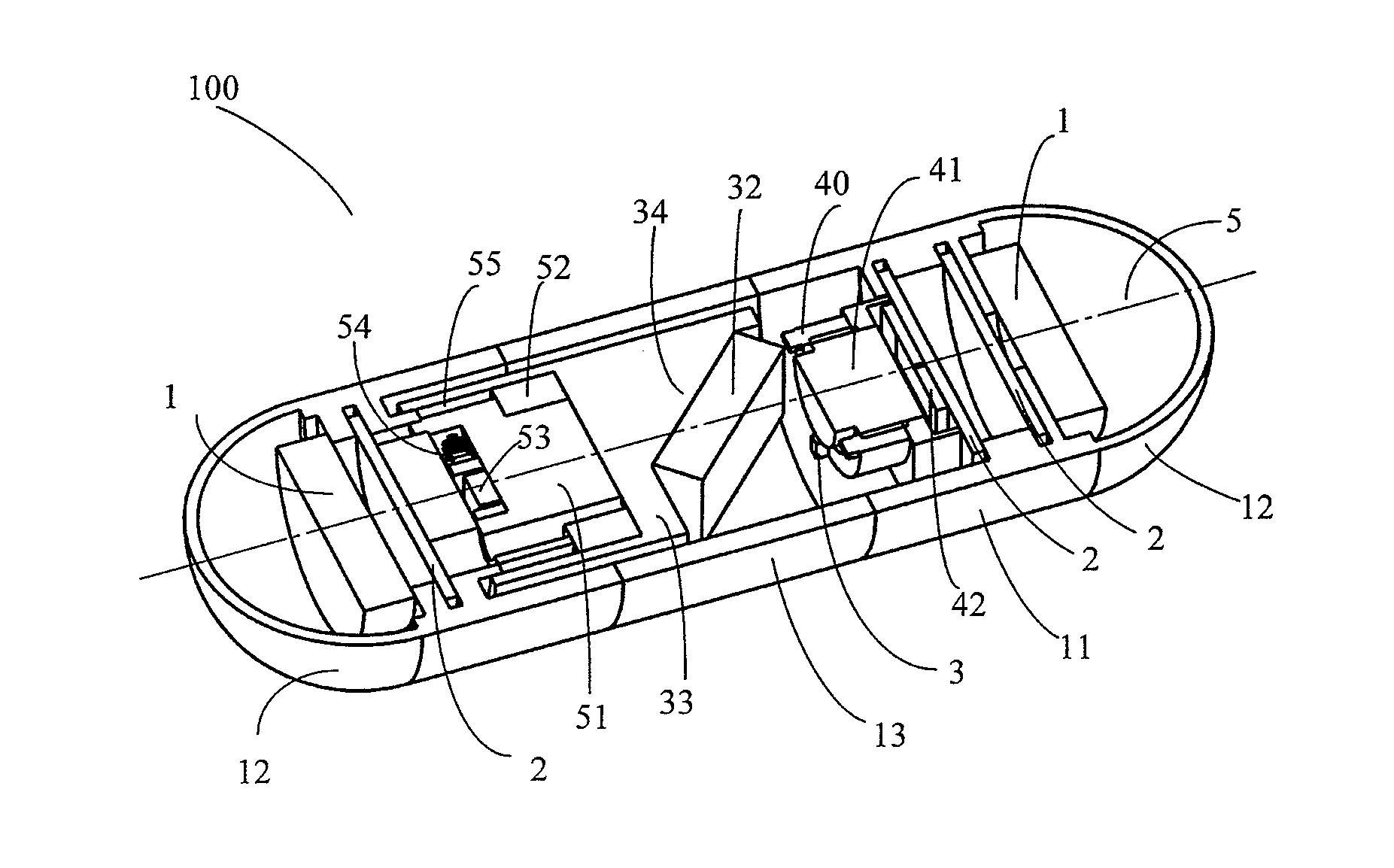
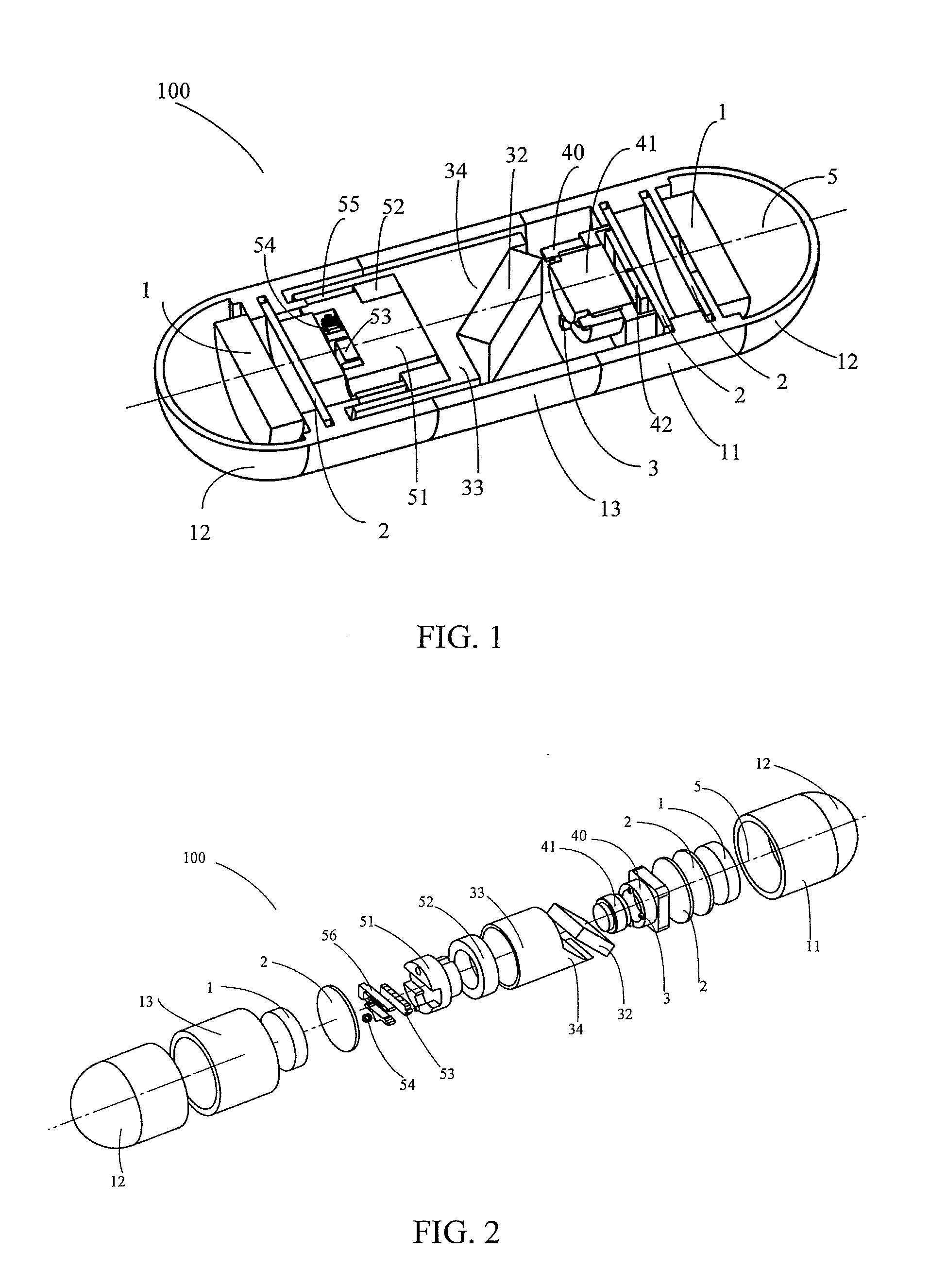
[0027]Referring firstly to FIG. 1 to FIG. 3, a capsule endoscope 100 according to the present invention comprises an enclosure housing a power source 1, one or more circuit boards 2, an illumination unit 3, a reflecting unit, an imaging unit, and a driving unit.
[0028]The enclosure comprises a tubular part 11 and a pair of semi-spherical end parts 12 formed at opposite ends of the tubular part 11. The tubular part 11 comprises a transparent section 13.
[0029]The illumination unit 3 may comprise a plurality of luminescent components, such as luminescent diodes or light emitting diodes. The illumination unit 3 is arranged to illuminate an object to be observed through the transparent section 13 of the tubular part 11.
[0030]The reflecting unit comprises a reflector mirror 32 and a mirror support seat for supporting the mirror 32. The support seat comprises a cylindrical body 33 and a slant mirror support part 34 extending from one end of the body 33. The cylindrical body 33 is coaxial wi...
second embodiment
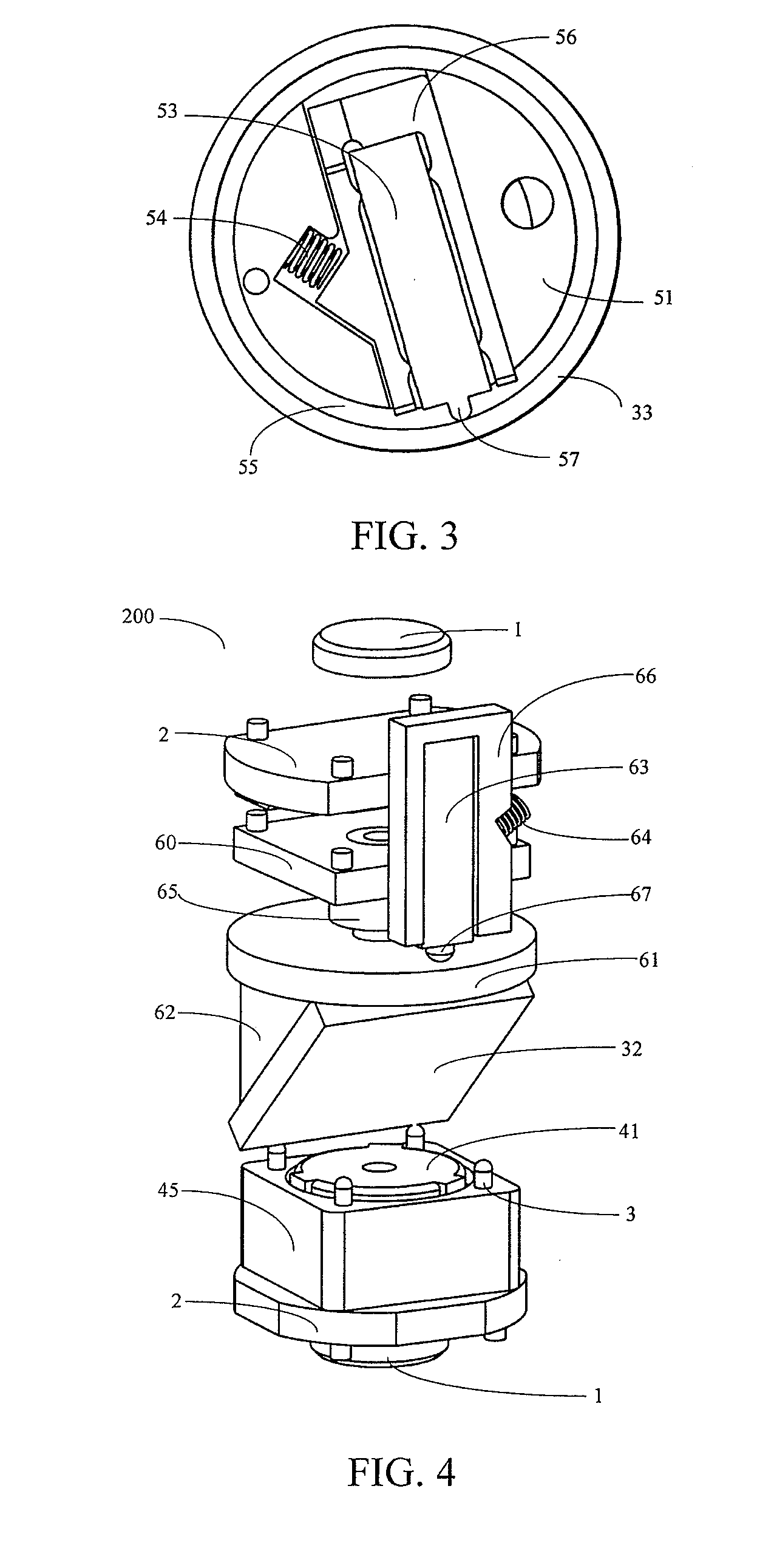
[0036]FIGS. 4 and 5 show another capsule endoscope 200 according to the present invention. The capsule endoscope 200 is similar to the capsule endoscope 100 except that the reflecting unit is pivotably mounted to a support bracket 60 which is fixed relative to the enclosure, the mirror support seat comprises a round plate 61 and a slant mirror support part 62 extending from one side of the plate 61 for supporting the mirror 32 thereon, a shaft extends from the opposite side of the plate 61 and pivotably supported in a bearing 65 which is fixed into an opening of the bracket 60, the motor seat 66 is disposed at the opposite side of the plate 61, the elastic member 64 urges the motor seat 66 to cause the nub 67 of the piezoelectric motor 63 to elastically press against the opposite side surface of the plate 61. When the piezoelectric motor 63 is energized the nub 67 of the piezoelectric motor 63 will rotate the plate 61 together with the mirror 32 about the axis 5 relative to the encl...
third embodiment
[0038]FIGS. 6 and 7 show a third capsule endoscope 300 according to the present invention. The difference between the third capsule endoscope 300 and the first capsule endoscope 100 is that in the third capsule endoscope 300 the reflecting unit is installed inside the hollow cylindrical body 71 of the support seat. The cylindrical body 71 has an opening facing the mirror 32 which is fixedly installed in the hollow cylindrical body 71 by the mirror seat 72. The support seat is pivotably attached to the enclosure by bearing 70. One end 75 of the cylindrical body 71 adjacent the image unit is open to allow the reflected light from the mirror 32 to pass there through to reach the image unit. The motor seat 76 is arranged in such a manner that the nub 77 of the piezoelectric motor 73 axially and resiliently pressed against the axial surface of the end 75 of the cylindrical body 71 under the pressure of the elastic member 74. When the piezoelectric motor 73 is energized the nub 77 of the ...
PUM
 Abstract
Description
Claims
Application Information