Micro-electromechanical system switch

Active Publication Date: 2010-06-24
GENERAL ELECTRIC CO
View PDF12 Cites 10 Cited by
  • Summary
  • Abstract
  • Description
  • Claims
  • Application Information

AI Technical Summary

Benefits of technology

[0011]In one embodiment, more than one pair of the in-plane and out-of-plan

Problems solved by technology

However, this increases the pull-in vol

Method used


Image

  • Micro-electromechanical system switch
  • Micro-electromechanical system switch
  • Micro-electromechanical system switch

Examples


Embodiment Construction

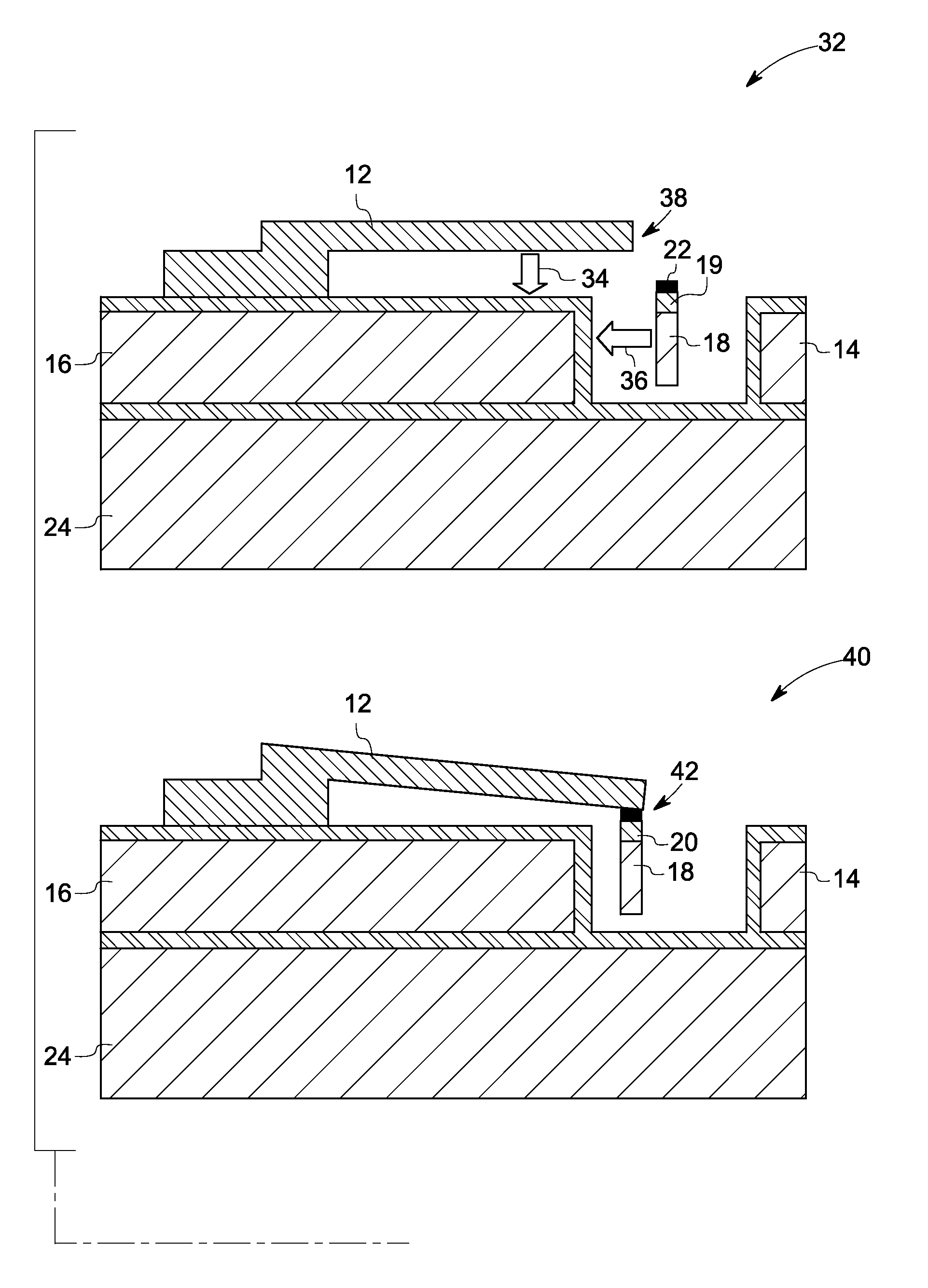
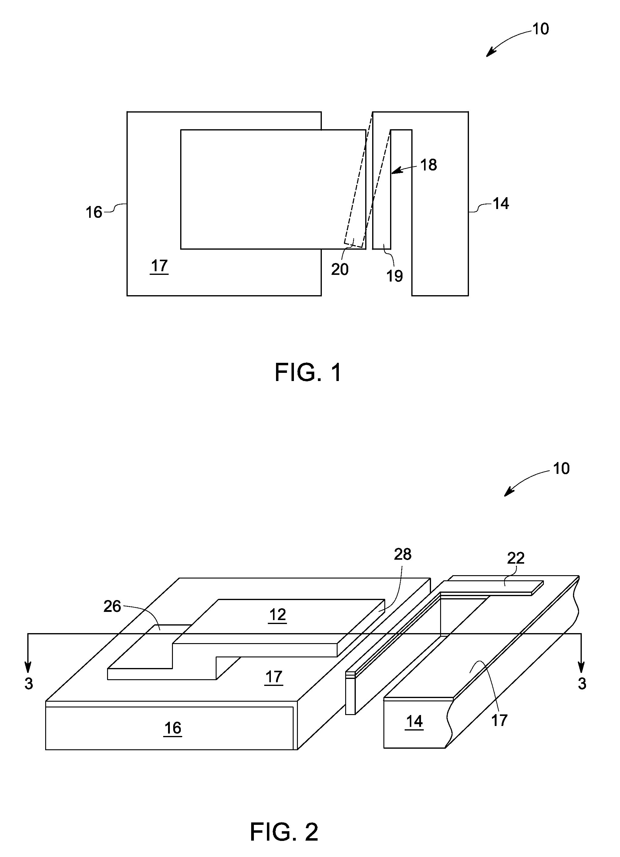
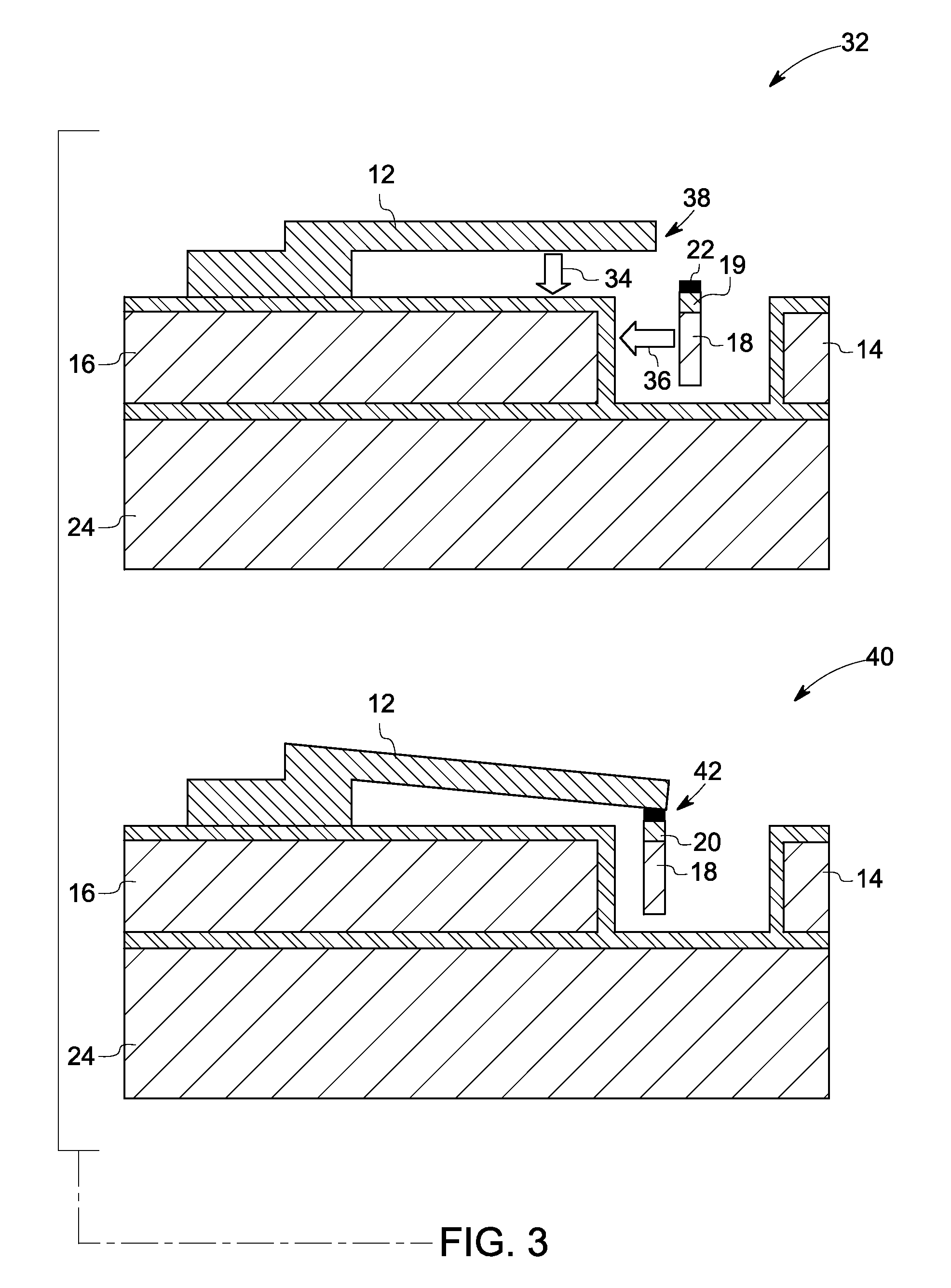
[0022]A MEMS switch can control electrical, mechanical, or optical signal flow. MEMS switches typically provide lower losses, and higher isolation. Furthermore MEMS switches provide significant size reductions, lower power consumption and cost advantages as compared to solid-state switches. MEMS switches also provide advantages such as broadband operation (can operate over a wide frequency range). Such attributes of MEMS switches significantly increase the power handling capabilities. With low loss, low distortion and low power consumption, the MEMS switches may be suited for applications such as telecom applications, analog switching circuitry, and switching power supplies. MEMS switches are also ideally suited for applications where high performance electro-mechanical, reed relay and other single function switching technologies are currently employed.

[0023]MEMS switches may employ one or more actuation mechanisms, such as electrostatic, magnetic, piezoelectric, or thermal actuatio...


PUM

PropertyMeasurementUnit
Forceaaaaaaaaaa
Areaaaaaaaaaaa
Mechanical propertiesaaaaaaaaaa

Abstract

A micro electromechanical system switch having an electrical pathway is presented. The switch includes a first portion and a second portion. The second portion is offset to a zero overlap position with respect to the first portion when the switch is in open position (or in the closed position depending on the switch architecture). The switch further includes an actuator for moving the first portion and the second portion into contact.

Description

BACKGROUND[0001]The invention relates generally to a switch and in particular, to a micro-electromechanical system switch.[0002]The use of micro-electromechanical system (MEMS) switches has been found to be advantageous over traditional solid-state switches. For example, MEMS switches have been found to have superior power efficiency, low insertion loss, and excellent electrical isolation.[0003]MEMS switches are devices that use mechanical movement to achieve a short circuit (make) or an open circuit (break) in a circuit. The force required for the mechanical movement can be obtained using various types of actuation mechanisms such as electrostatic, magnetic, piezoelectric, or thermal actuation. Electrostatically actuated switches have been demonstrated to have high reliability and wafer scale manufacturing techniques. Construction and design of such MEMS switches have been constantly improving.[0004]Switch characteristics such as standoff voltage (between the contacts of the switch...

Claims


Application Information

Patent Timeline
IPC IPC(8): H01H57/00H01H11/00
CPCH01H1/0036H01H59/0009Y10T29/49105H01H2001/0084H01H2001/0078H01H36/00H01H2237/004
Inventor WANG, XUEFENGCORWIN, ALEX DAVIDLI, BOSUBRAMANIAN, KANAKASABAPATHIKISHORE, KUNA VENKAT SATYA RAMA
Owner GENERAL ELECTRIC CO
Why Eureka
Try Eureka