
Ice skate runner

a technology of ice skates and runners, which is applied in the direction of skis, ski-brakes, skates, etc., can solve the problems of runner being relatively heavy, requiring blade improvements, and generally heavy steel blades

Active Publication Date: 2010-07-15
SPORT MASKA
View PDF36 Cites 28 Cited by
  • Summary
  • Abstract
  • Description
  • Claims
  • Application Information

AI Technical Summary

Benefits of technology

[0008]It is therefore an aim of the present description to provide an improved ice skate runner.
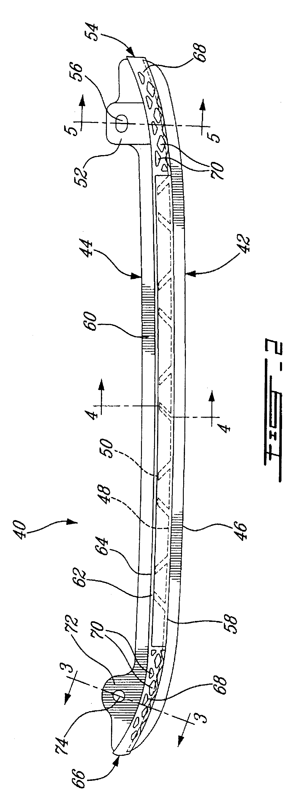
[0009]Therefore, in accordance with an aspect of the present invention, there is provided an ice skate runner for detachable engagement in a blade holder of an ice skate, the blade holder having an opening therein for receiving at least a portion of the runner and fastening means to retain the runner in place, the runner comprising: an upper polymeric portion shaped to be partially received within the opening of the blade holder, the upper polymeric portion defining a major part of the runner; a lower portion having a greater density than that of the upper portion and defining a blade surface for engaging the ice; and at least one of the upper and lower portions being shaped to removably engage the fastening means.

Problems solved by technology

However, such steel blades are generally heavy and represent a significant part of the weight of the skate.
However, the necessity for the special holders and / or fastening means generally prevents such blade improvements to be used on more conventional skates having holders manufactured to receive standard, typical planar steel blades.
However, as the steel portion of the blade extends through almost the entire runner, the runner is still relatively heavy.

Method used


Image

  • Ice skate runner
  • Ice skate runner
  • Ice skate runner

Examples


Embodiment Construction

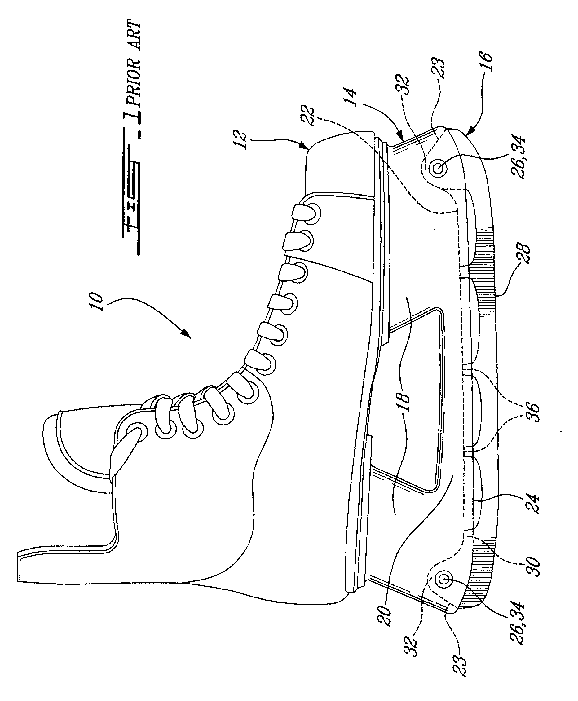
[0024]Referring to FIG. 1, a typical ice skate is generally shown at 10. The skate 10 comprises a skate boot 12 adapted to receive a foot therein, a blade holder 14 attached under the boot 12, and a replaceable blade 16 received within the holder 14. The holder 14 includes attachment portions 18 extending from the skate boot 12 and a bottom portion 20 extending between the attachment portions 18 along the length of the skate 10. The attachment portions 18 and the bottom portion 20 include a vertically extending elongated slot 22 defined in a bottom surface 24 thereof, which can be machined into the holder 14 or alternately integrally molded therewith. The slot 22 does not comprise any reinforcing material, such as steel, aluminum, composite materials, or others. The attachment portions 18 each include fastening means, which in the embodiment shown include the slot 22 having enlarged, rounded ends 23 in each attachment portion 18, and a hole 26 defined through each attachment portion...


PUM


Abstract

An ice skate runner for engagement in a blade holder of an ice skate, the blade holder having an opening defined along a bottom edge thereof and fastening means to retain the runner. The runner comprises an upper polymeric portion shaped to be partially received within the opening of the holder and defining a major part of the runner, a lower portion having a greater density than that of the upper portion and defining a lower blade surface for engaging the ice. At least one of the upper and lower portions is shaped to removably engage the fastening means.

Description

CROSS-REFERENCE TO RELATED APPLICATIONS[0001]This application claims priority on U.S. Provisional Patent Application Nos. 60 / 907,337 filed on Mar. 29, 2007; 60 / 924,634 filed on May 23, 2007; and 61 / 016,068 filed on Dec. 21, 2007 which are incorporated by reference.FIELD OF THE INVENTION[0002]The present object relates to sports equipment with blades, and in particular to ice skates having replaceable blades.BACKGROUND ART[0003]As skate boots are generally more durable than skate blades, also known as runners, it is known to provide skates with planar steel blades detachably received within a holder of the skate, such that the blades can be easily replaced when worn out. However, such steel blades are generally heavy and represent a significant part of the weight of the skate.[0004]As the performance of a skate can be substantially influenced by its weight, a number of skate and blade designs have been created with the goal of minimizing the weight of the skate. Skates having thin me...

Claims


Application Information

Patent Timeline
IPC IPC(8): A63C1/00A63C1/32
CPCA63C1/32
Inventor KOYESS, PHILIPPECHRETIEN, ALEXANDRE
Owner SPORT MASKA
Learn More