
Self-closing slide assembly with dampening mechanism

a self-closing, slide technology, applied in mechanical devices, furniture parts, manufacturing tools, etc., can solve the problems of occupying valuable space within the slide mechanism, slamming against the cabinet structure and re-opening, damage to the drawer structure or slide mechanism,

Active Publication Date: 2010-07-15
JONATHAN MFG
View PDF15 Cites 13 Cited by
  • Summary
  • Abstract
  • Description
  • Claims
  • Application Information

AI Technical Summary

Benefits of technology

[0009]Accordingly, preferred embodiments of the present invention provide an improved slide assembly with dampened, self-closing motion.
[0013]A slide assembly includes an outer slide segment and an inner slide segment. The outer slide segment defines a wall portion and a pair of bearing surfaces spaced from one another on opposite sides of the wall portion. An inner slide segment is operably supported by the bearing surfaces of the outer segment. The inner slide segment is movable relative to the outer slide segment between an open position and a closed position. A self-closing mechanism is coupled to the outer slide segment and configured to automatically move the inner slide segment in a closing direction towards the closed position when the inner segment is moved to within a predetermined distance from the closed position. The self-closing mechanism includes a carrier that is slidably supported relative to the outer slide segment by the bearing surfaces. A latch is carried by the carrier, wherein the latch selectively engages the inner slide segment such that the carrier and the inner slide segment move together relative to the outer slide segment. A biasing mechanism urges the carrier in the closing direction. A dampener produces a dampening force tending to oppose movement of the carrier. A guide slot is defined by the wall of the outer slide segment and assists in engagement and disengagement of the latch from the inner slide segment.
[0014]A slide assembly includes a first slide segment defining at least one bearing surface and a second slide segment operably supported by the bearing surface of the first slide segment. The second slide segment is able to move relative to the first slide segment between a closed position and an open position. A self-closing mechanism automatically moves the second slide segment in a closing direction towards the closed position when the second segment is moved to within a predetermined distance from the closed position. The self-closing mechanism includes a carrier that engages the second slide segment and a dampener that dampens the motion of the carrier. The carrier is slidably supported by the bearing surface of the first slide segment.
[0015]In accordance with one embodiment, the closing mechanism includes a movable latch assembly which engages a slot on the inner segment. One or more springs are configured to provide tension between the outer segment and the latch assembly. A dampener is configured to provide a dampening effect to the self-closing motion between the latching assembly and the outer segment.

Problems solved by technology

In certain situations, drawers may tend to open after they are closed and sometimes drawers do not close completely when they are pushed closed because they are not pushed with sufficient force or they are pushed closed with more force than necessary.
When excessive force is used to close a drawer, it can cause the drawer to slam against the cabinet structure and re-open.
Also, when drawers are closed with excessive force, it can damage the drawer structure or slide mechanism.
However, existing slide mechanisms designed to automatically close a drawer can be bulky and can cause the slide mechanism to take up valuable space within the cabinet or drawer structure, especially in the width direction.
Existing mechanisms that control the drawer closing process can also be very complicated and can add significant cost to the slide assembly.

Method used


Image

  • Self-closing slide assembly with dampening mechanism
  • Self-closing slide assembly with dampening mechanism
  • Self-closing slide assembly with dampening mechanism

Examples


Embodiment Construction

[0026]In the following detailed description, terms of orientation such as “top,”“bottom,”“upper,”“lower,”“front,”“frontward,”“rear,”“rearward,” and “end” are used to simplify the description of the context of the illustrated embodiments. Likewise, terms of sequence, such as “first” and “second,” are used to simplify the description of the illustrated embodiments. However, other orientations and sequences are possible, and the present invention should not be limited to the illustrated orientation(s). Those skilled in the art will appreciate that other orientations of the various components are possible.

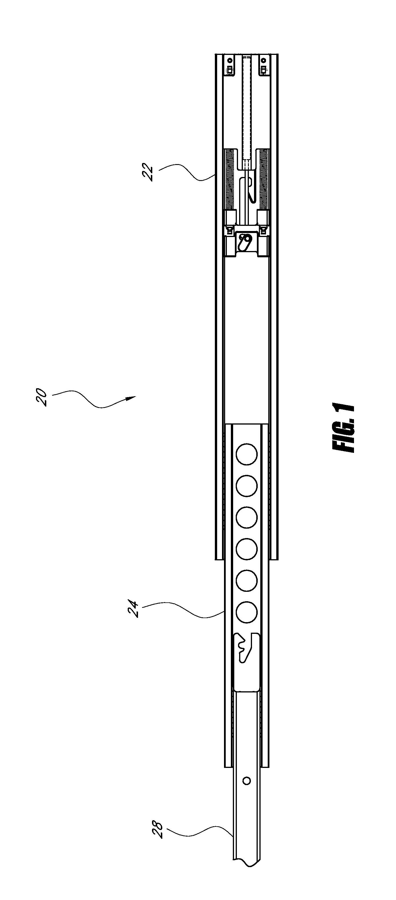
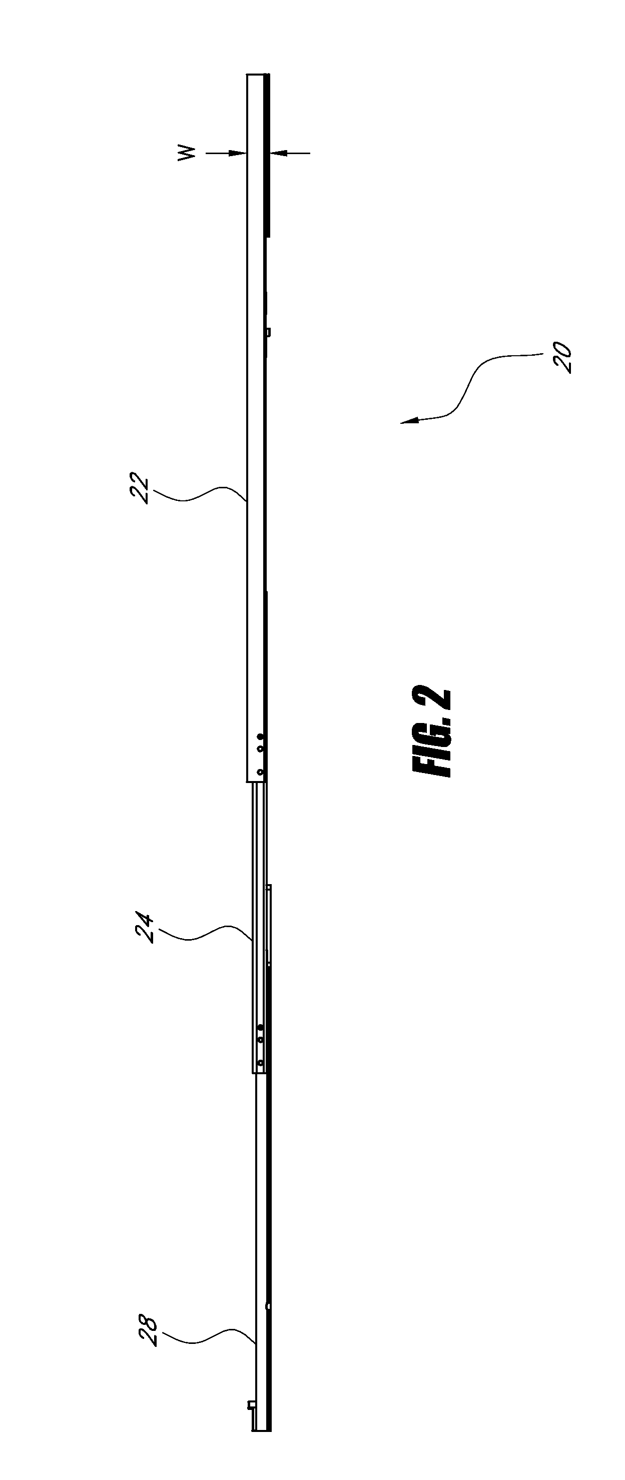
[0027]FIG. 1 illustrates an embodiment of a slide assembly 20 including an outer slide segment 22 and an inner slide segment 28 operably supported by the outer segment 22. The illustrated slide assembly 20 also includes an intermediate segment 24 interposed between the outer slide segment 22 and the inner slide segment 28. In other arrangements, the slide assembly 20 can include one or...


PUM


Abstract

A slide assembly with a self-closing mechanism that includes a dampening mechanism. In one arrangement, the slide assembly includes an inner slide segment slidably coupled to an outer slide segment. The self-closing mechanism is configured to move the inner slide segment towards a retracted position when the inner segment is moved to within a predetermined distance from the retracted position. The slide assembly can also include a latch which is engaged during the closing process and functions to trigger the self-closing and dampening. In an arrangement, the slide assembly has a maximum width dimension of about 0.4 inches or less, taking into account normal manufacturing variations. In an arrangement, a movable portion of the self-closing mechanism slidably engages a bearing race of the outer segment.

Description

RELATED APPLICATIONS[0001]This application claims benefit under 35 U.S.C. §119(e) to U.S. Provisional Patent Application No. 61 / 143,740, filed Jan. 9, 2009, entitled SELF-CLOSING SLIDE ASSEMBLY WITH DAMPENING MECHANISM, the entirety of which is hereby incorporated by reference herein and made part of this specification.BACKGROUND OF THE INVENTION[0002]1. Field of the Invention[0003]The present invention relates to slide assemblies, and more particularly to compact self-closing slide assemblies with dampening of the self-closing motion.[0004]2. Description of the Related Art[0005]Slide assemblies typically comprise two or more slide segments. In slide assemblies comprising only two slide segments, a first or outer slide segment may be mounted to a frame of a support structure, such as a cabinet or a rack structure, and a second or inner slide segment may be mounted to a movable object, such as a drawer or an internet server, for example. The outer slide segment defines a channel. The...

Claims


Application Information

Patent Timeline
Patent Type & Authority Applications(United States)
IPC IPC(8): A47B88/12E05F5/06F16C29/02
CPCY10T16/625A47B88/047A47B88/467
Inventor PEREZ, RAMIRO A.JUDGE, RONALD J.BROCK, PATTY J.
Owner JONATHAN MFG
Learn More