Hierarchical rate color marker

a color marker and hierarchy technology, applied in the field of computer networking, can solve the problems of limited number of overflow medium inability to guarantee cos b>1/b>, limited number of overflow high-compliance tokens distributed to a respective cos level, etc., to facilitate bandwidth-profile enforcement

a color marker and hierarchy technology, applied in the field of computer networking, can solve the problems of limited number of overflow medium inability to guarantee cos b>1/b>, limited number of overflow high-compliance tokens distributed to a respective cos level, etc., to facilitate bandwidth-profile enforcement

US20100177635A1Active Publication Date: 2010-07-15AVAGO TECH INT SALES PTE LTD

Image

  • Hierarchical rate color marker
  • Hierarchical rate color marker
  • Hierarchical rate color marker

Examples


Embodiment Construction

Overview

[0054]In embodiments of the present invention, the problem of re-using unused guaranteed and best-effort bandwidth in a virtual circuit is solved by distributing the bandwidth to a different class of service or converting guaranteed bandwidth to best-effort bandwidth and distributing the converted bandwidth to one or more classes of service.

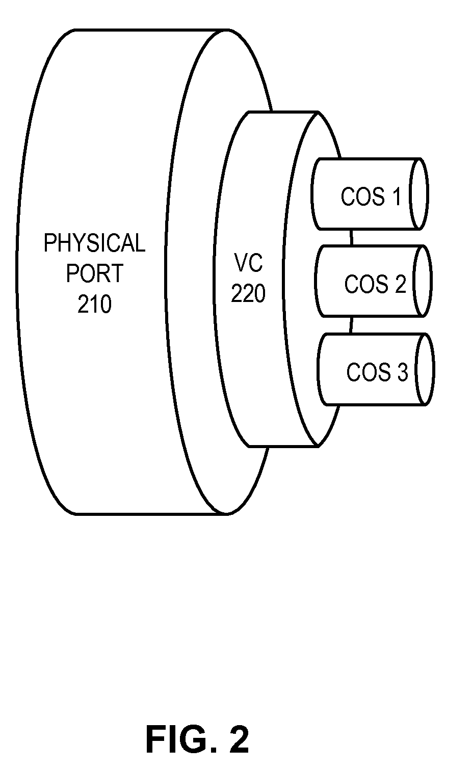
[0055]Specifically, in the scenario illustrated earlier, to address the problem that there is no guarantee that CoS 1 will have all of its 4 Mb / s of traffic marked green on average, a hierarchical bandwidth profile and a hierarchical rate color maker are desirable. Consider a hierarchical rate color maker with CIR=6 Mb / s and EIR=4 Mb / s for a VC containing CoS 1, 2, and 3 with 4 Mb / s of traffic each on average. In addition, the hierarchical rate color marker guarantees that CIR is divided among the classes of service such that CoS 1 receives 3 Mb / s of CIR, CoS 2 receives 2 Mb / s of CIR, and CoS 3 receives 1 Mb / s of CIR. In addition, EIR is ...


PUM


Abstract

One embodiment provides a system that facilitates bandwidth-profile enforcement. During operation, the system indicates a packet's compliance with a bandwidth profile based at least on available high-compliance tokens and medium-compliance tokens. The system further accounts for overflow tokens from a respective class of service (CoS) and distribute an overflow token to another CoS priority level based on the overflow token's CoS information.

Description

RELATED APPLICATION[0001]This application claims the benefit of:[0002]U.S. Provisional Application No. 61 / 143,585, Attorney Docket Number FDRY-0196-PROV-US, entitled “Hierarchical Rate Color Marker,” by inventor Norival R. Figueira, filed on 9 Jan. 2009;[0003]U.S. Provisional Application No. 61 / 146,477, Attorney Docket Number FDRY-0197-PROV-US, entitled “Enhanced Hierarchical Rate Color Marker,” by inventor Norival R. Figueira, filed on 22 Jan. 2009;[0004]U.S. Provisional Application No. 61 / 225,483, Attorney Docket Number FDRY-0197.1-PROV-US, entitled “Hierarchical Rate Color Marker Supporting Weighted Round Robin Distribution of Unused Bandwidth,” by inventor Norival R. Figueira, filed on 14 Jul. 2009;[0005]U.S. Provisional Application No. 61 / 251,139, Attorney Docket Number FDRY-0197.2-PROV-US, entitled “Hierarchical bandwidth Profile Algorithm Implementation,” by inventor Norival R. Figueira, filed on 13 Oct. 2009; and[0006]U.S. Provisional Application No. 61 / 253,791, Attorney Doc...

Claims


Application Information

Patent Timeline
15 Jul 2010
Publication
US20100177635A1
IPC
H04L12/56; H04L47/525; H04L47/20; H04L47/21; H04L47/31
CPC
H04L47/10; H04L47/20; H04L47/215; H04L47/60; H04L47/2441; H04L47/31; H04L47/525; H04L47/2425
Inventors
FIGUEIRA, NORIVAL R.