Sound reproducing apparatus using in-ear earphone

Active Publication Date: 2010-07-15
PANASONIC INTELLECTUAL PROPERTY CORP OF AMERICA
View PDF11 Cites 28 Cited by
  • Summary
  • Abstract
  • Description
  • Claims
  • Application Information

AI Technical Summary

Benefits of technology

[0018]According to the present invention, a characteristic of an ear canal of an individual is measured by using an earphone used for listening, and thereby an optimum ear-canal correction filter can be obtain

Problems solved by technology

On the other hand, since wearing an earphone in an ear blocks an ear canal, there arises a pr

Method used


Image

  • Sound reproducing apparatus using in-ear earphone
  • Sound reproducing apparatus using in-ear earphone
  • Sound reproducing apparatus using in-ear earphone

Examples


first embodiment

[0060

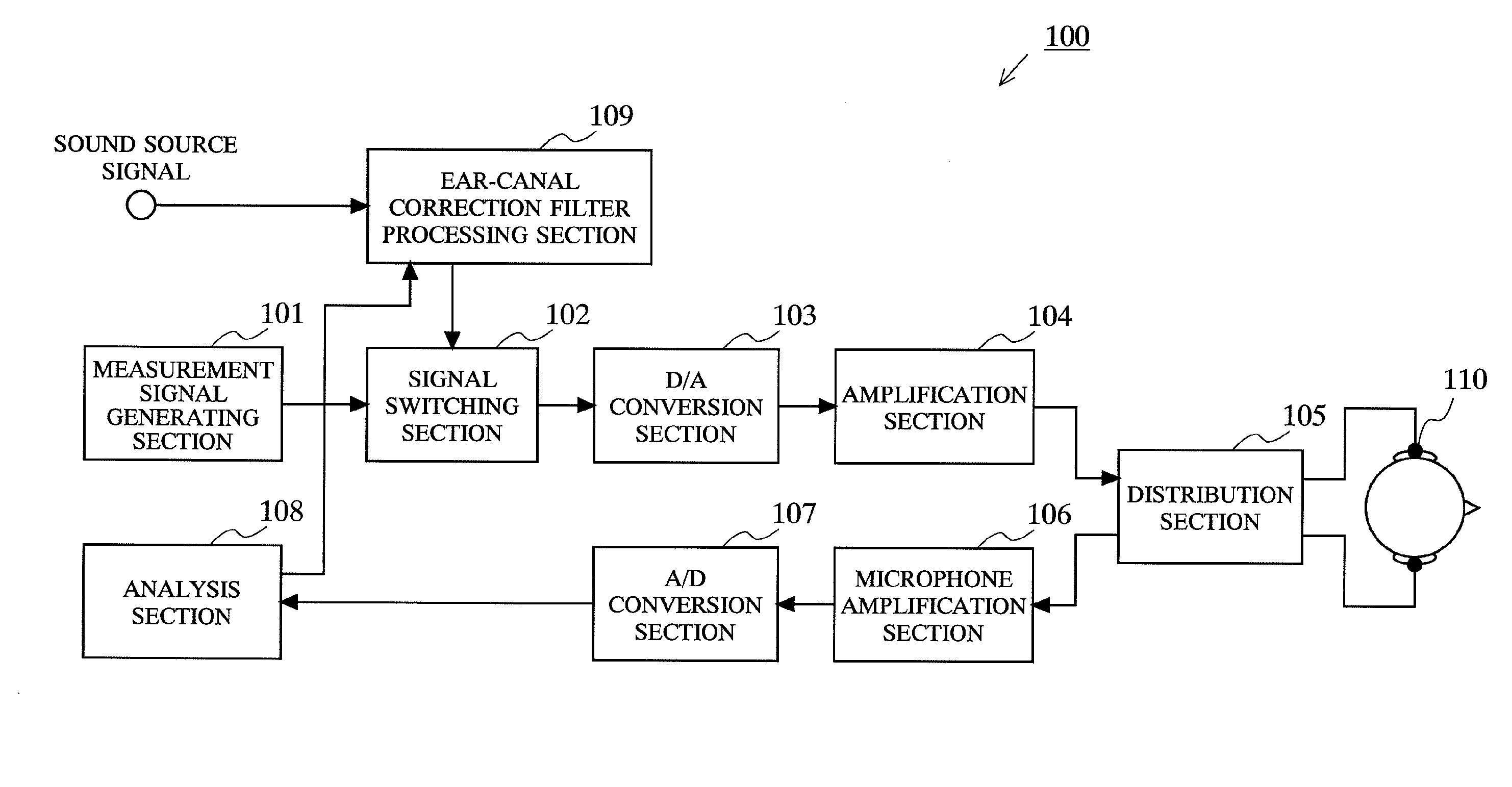
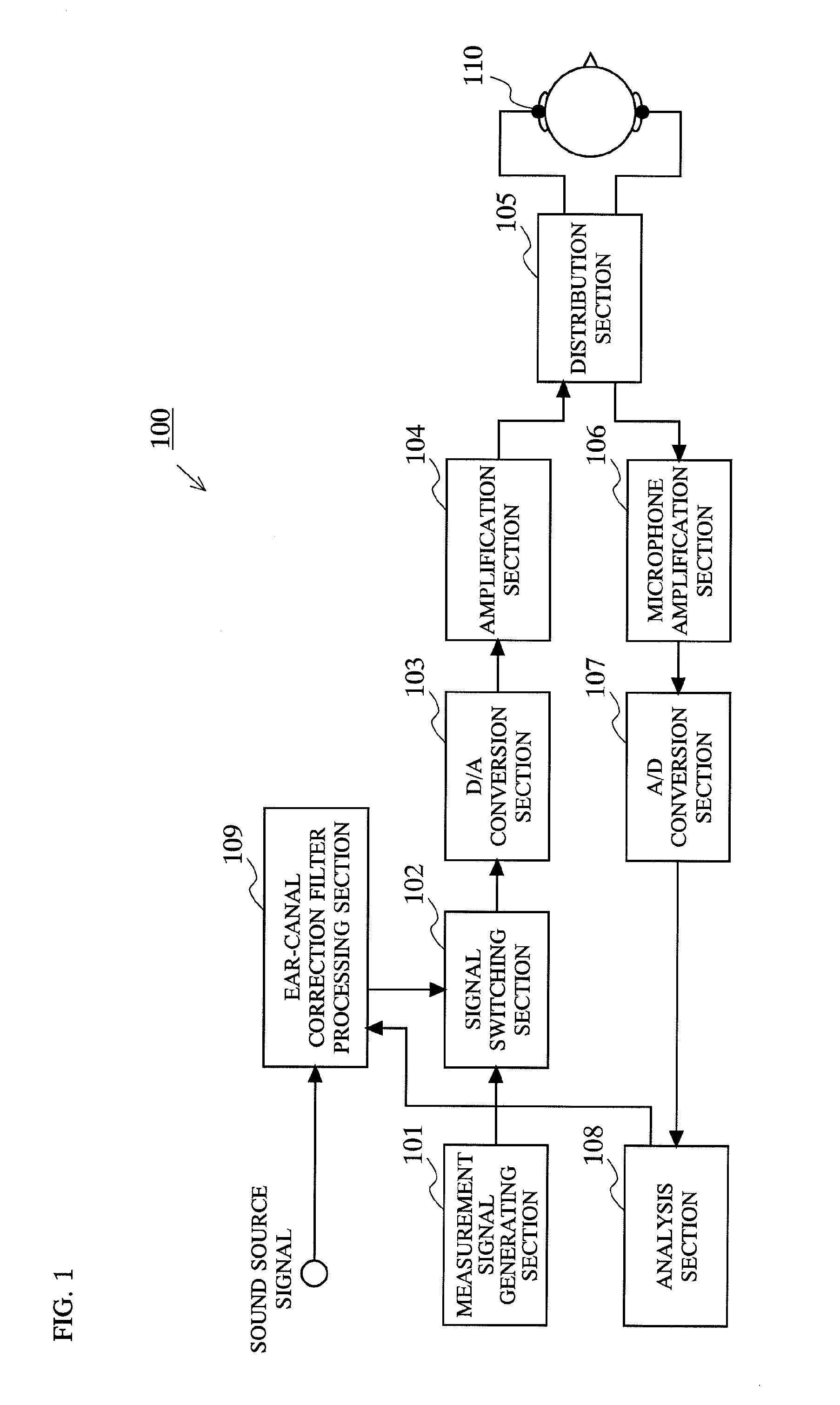
[0061]FIG. 1 shows a configuration of a sound reproducing apparatus 100 according to a first embodiment of the present invention. As shown in FIG. 1, the sound reproducing apparatus 100 includes a measurement signal generating section 101, a signal switching section 102, a D / A conversion section 103, an amplification section 104, a distribution section 105, a microphone amplification section 106, an A / D conversion section 107, an analysis section 108, an ear-canal correction filter processing section 109, and an earphone 110. The signal switching section 102, the D / A conversion section 103, the amplification section 104, the distribution section 105, the microphone amplification section 106, and the A / D conversion section 107 constitute a signal processing section 111.

[0062]Firstly, an outline of each component of the sound reproducing apparatus 100 according to the first embodiment will be described.

[0063]The measurement signal generating section 101 generates a measurement si...

second embodiment

[0084

[0085]FIG. 6 shows a configuration of a sound reproducing apparatus 200 according to a second embodiment of the present invention. As shown in FIG. 6, the sound reproducing apparatus 200 includes the measurement signal generating section 101, the signal processing section 111, the analysis section 108, the ear-canal correction filter processing section 109, the earphone 110, and an HRTF processing section 212.

[0086]As shown in FIG. 6, the sound reproducing apparatus 200 according to the second embodiment is different from the sound reproducing apparatus 100 according to the first embodiment, with respect to the HRTF processing section 212. Hereinafter, the sound reproducing apparatus 200 will be described focusing on the HRTF processing section 212 which is the difference. The same components as those of the sound reproducing apparatus 100 are denoted by the same reference numerals and description thereof is omitted.

[0087]When a reproduction of the sound source signal is starte...

third embodiment

[0090

[0091]FIG. 7 shows a configuration of a sound reproducing apparatus 300 according to a third embodiment of the present invention. As shown in FIG. 7, the sound reproducing apparatus 300 includes the measurement signal generating section 101, the signal processing section 111, an analysis section 308, the ear-canal correction filter processing section 109, and the earphone 110. FIG. 8 shows a detailed example of a configuration of the analysis section 308. As shown in FIG. 8, the analysis section 308 includes the FFT processing section 114, the memory section 115, the coefficient calculation section 116, the IFFT processing section 117, a convolution processing section 318, and an HRTF storage section 319.

[0092]The sound reproducing apparatus 300 according to the third embodiment shown in FIG. 7 and FIG. 8 is different from the sound reproducing apparatus 100 according to the first embodiment, with respect to the convolution processing section 318 and the HRTF storage section 31...


PUM


Abstract

First, in a state where a pair of earphones 110 are worn in both ears of a listening person, a measurement signal generated by a measurement signal generating section 101 is outputted from the earphone 110. The signal (wearing-state signal) which is reflected by an eardrum and returns to the earphone 110 is measured, and stored in an analysis section 108. Next, in a state where the pair of earphones 110 are not worn in both ears of the listening person, a signal measured (unwearing-state signal) in the same manner as described above is stored in the analysis section 108. The analysis section 108 calculates an ear-canal correction filter based on a difference between the wearing-state signal and the unwearing-state signal. An ear-canal correction filter processing section 109 convolves a sound source signal with the calculated ear-canal correction filter.

Description

TECHNICAL FIELD[0001]The present invention relates to a sound reproducing apparatus for reproducing a sound by using an in-ear earphone.BACKGROUND ART[0002]A sound reproducing apparatus using an in-ear earphone is compact, highly portable, and useful. On the other hand, since wearing an earphone in an ear blocks an ear canal, there arises a problem that the sound is slightly muffled and that it is difficult to obtain a spacious sound.[0003]For example, let it be assumed that the ear canal of an ear is represented by a simple cylindrical model. When not wearing an earphone in the ear, the cylinder is closed at the eardrum side and is open at the entrance side of the ear, that is, one end of the cylinder is open and the other end is closed ((a) in FIG. 16). In this case, a primary resonance frequency is about 3400 Hz if it is assumed that the length of the cylinder is 25 mm which is an average length of the ear canal of a human. On the other hand, when wearing an earphone 110 in the e...

Claims


Application Information

Patent Timeline
IPC IPC(8): H04B15/00
CPCH04R5/04H04R5/033H04R1/1016H04R3/04H04R25/70H04R2460/05
Inventor WATANABE, YASUHITO
Owner PANASONIC INTELLECTUAL PROPERTY CORP OF AMERICA
Why Eureka
Try Eureka