
Side positioned vision enhancement device mount

a technology for eye enhancement devices and mounts, which is applied in the direction of curtain suspension devices, furniture parts, machine supports, etc., can solve the problems of imposing additional strain on the user's neck, and the drawbacks of conventional head or helmet mounts for eye enhancement devices

Inactive Publication Date: 2010-07-22
EXCELIS INC
View PDF16 Cites 24 Cited by
  • Summary
  • Abstract
  • Description
  • Claims
  • Application Information

AI Technical Summary

Benefits of technology

[0003]The drawbacks of conventional head or helmet mounts are resolved in many respects by device mounts of the present invention. In one aspect of the invention, a device mount for mounting a vision enhancement device to an article worn on a user's head includes a first adjustment member operable to move a mounted vision enhancement device in a cranial-caudal direction with respect to the

Problems solved by technology

The storage position of the device is far above the user's head, creating a conspicuous profile that is a snag hazard and imposes additional strain on the user's neck.
For these reasons, conventional head or helmet mounts for vision enhancement devices have significant drawbacks.

Method used


Image

  • Side positioned vision enhancement device mount
  • Side positioned vision enhancement device mount
  • Side positioned vision enhancement device mount

Examples


Embodiment Construction

[0021]Although the invention is illustrated and described herein with reference to specific embodiments, the invention is not intended to be limited to the details shown. Rather, various modifications may be made in the details within the scope and range of equivalents of the claims and without departing from the invention.

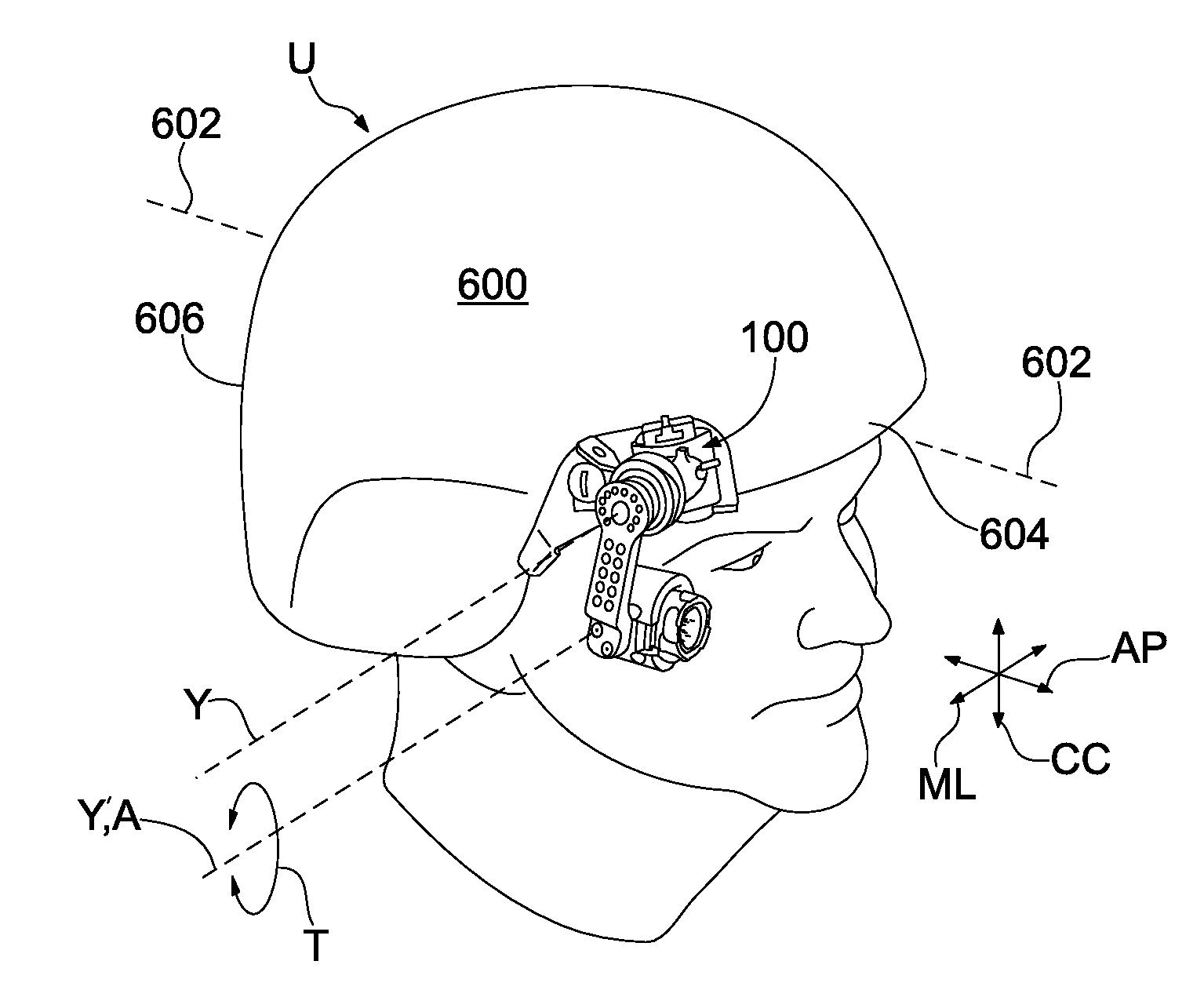
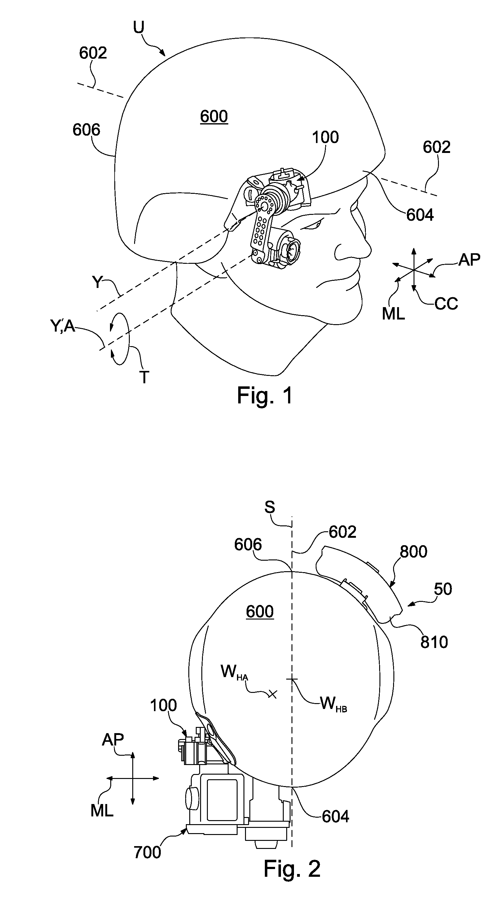
[0022]Device mounts in accordance with the invention resolve a number of drawbacks observed with conventional mounting systems for vision enhancement devices. Referring to FIG. 1, a device mount 100 for mounting a vision enhancement device is shown on a helmet body 600 worn by a user U. Device mount 100 is mounted at a position that is offset to one side of helmet 600, i.e., to one side of an axis 602 that extends between an anterior end 604 and a posterior end 606 of helmet 600. A portion of device mount 100 is aligned with the user's interpupillary axis A, i.e. an axis extending through both of the user's pupils. In this arrangement, device mount 100 can mount a...


PUM


Abstract

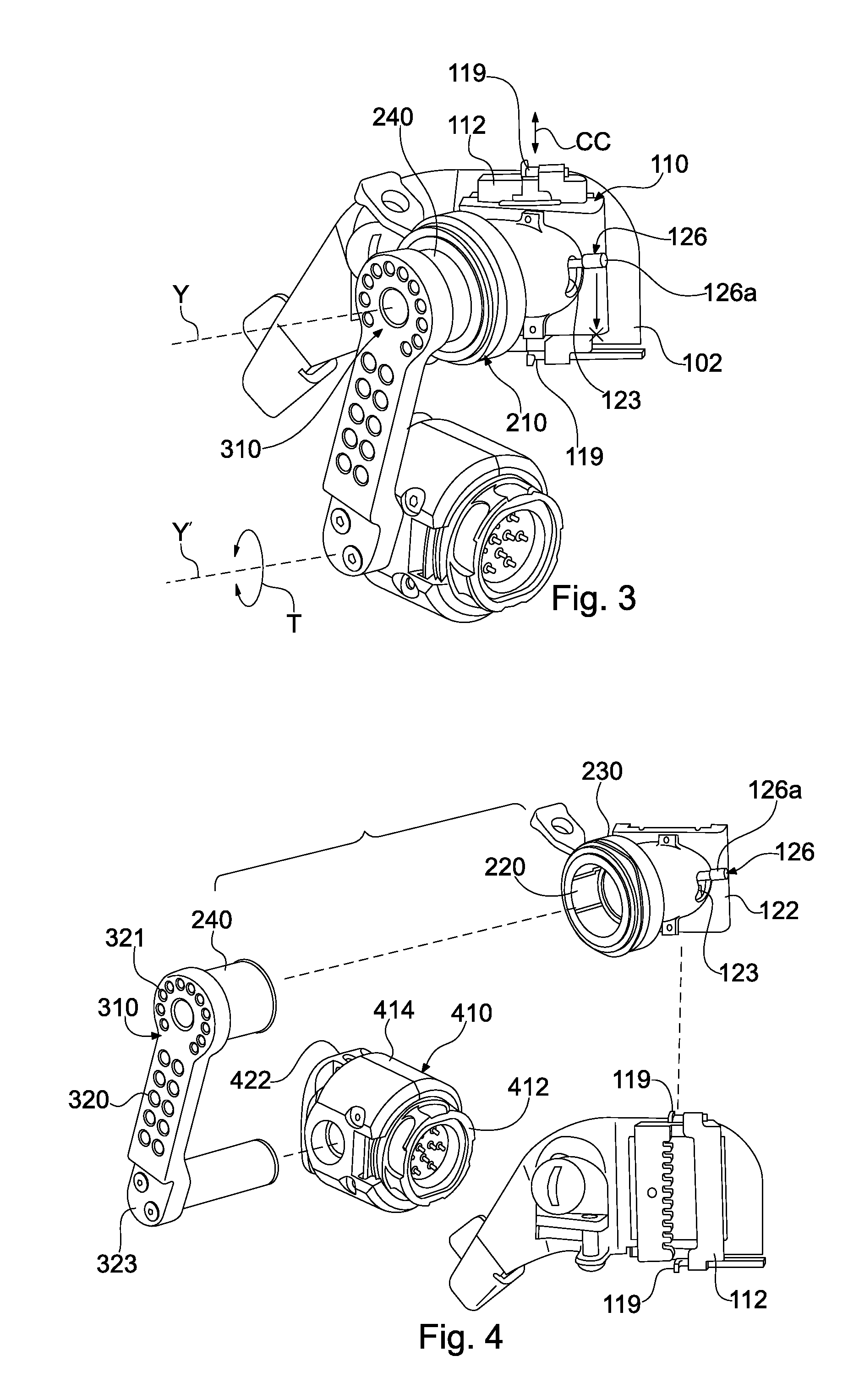
A device mount for mounting a vision enhancement device to an article worn on a user's head includes a first adjustment member operable to move a mounted vision enhancement device in a cranial-caudal direction with respect to the user. A second adjustment member which extends from the first adjustment member is operable to move a mounted vision enhancement device along a medial-lateral adjustment axis with respect to the user. A third adjustment member includes an extension arm extending from the second adjustment member that rotates with respect to the medial-lateral adjustment axis of the second adjustment member. A helmet apparatus includes a device mount and power supply that are offset from an anterior-posterior axis of the helmet in a counterbalancing arrangement.

Description

FIELD OF THE INVENTION[0001]The present invention relates generally to head mounted equipment for vision enhancement and more specifically to a mounting assembly for mounting vision enhancement equipment to a helmet or other article worn on the head.BACKGROUND OF THE INVENTION[0002]Head or helmet mounts allow vision enhancement devices, such as direct view goggles or displays for cameras, to be mounted on the head or helmet in front of a user's eye. The user can view his or her surroundings through the vision enhancement device, while keeping his or her hands free to perform various tasks. Typical mounts are positioned on the helmet, head harness or other article so that the vision enhancement device is mounted centrally over the user's forehead. This central positioning results in a large overhanging structure that is relatively heavy, with a large forward projection. The storage position of the device is far above the user's head, creating a conspicuous profile that is a snag haza...

Claims


Application Information

Patent Timeline
IPC IPC(8): A42B1/24A47B96/06
CPCA42B3/042
Inventor WILLEY, CHARLES D.BANDY, GREGORY S.SCHLIRF, KEVIN C.
Owner EXCELIS INC
Learn More