Spring track roller assembly

US20100187367A1Active Publication Date: 2010-07-29THE BOEING CO

Image

  • Spring track roller assembly
  • Spring track roller assembly
  • Spring track roller assembly

Examples


Embodiment Construction

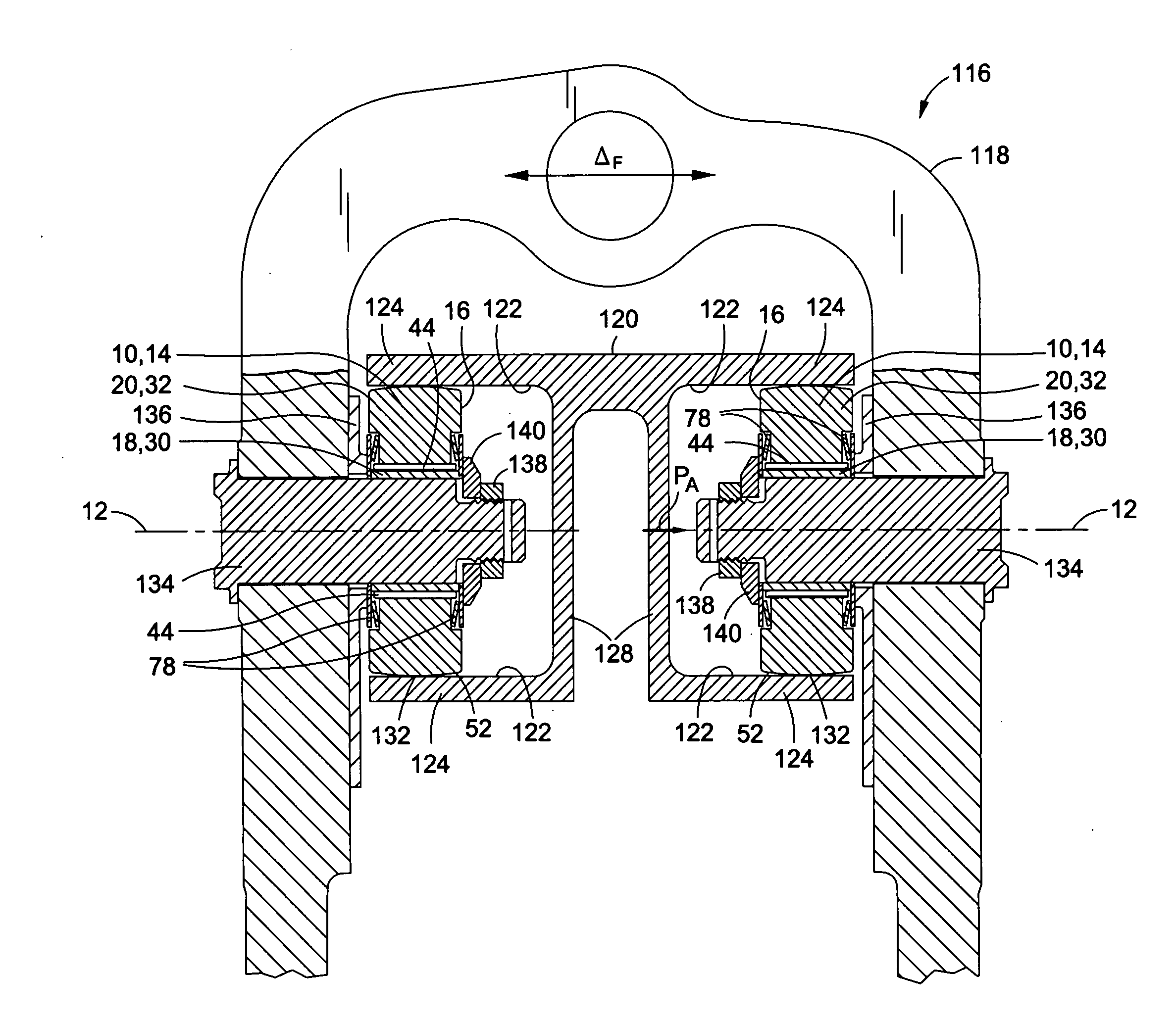
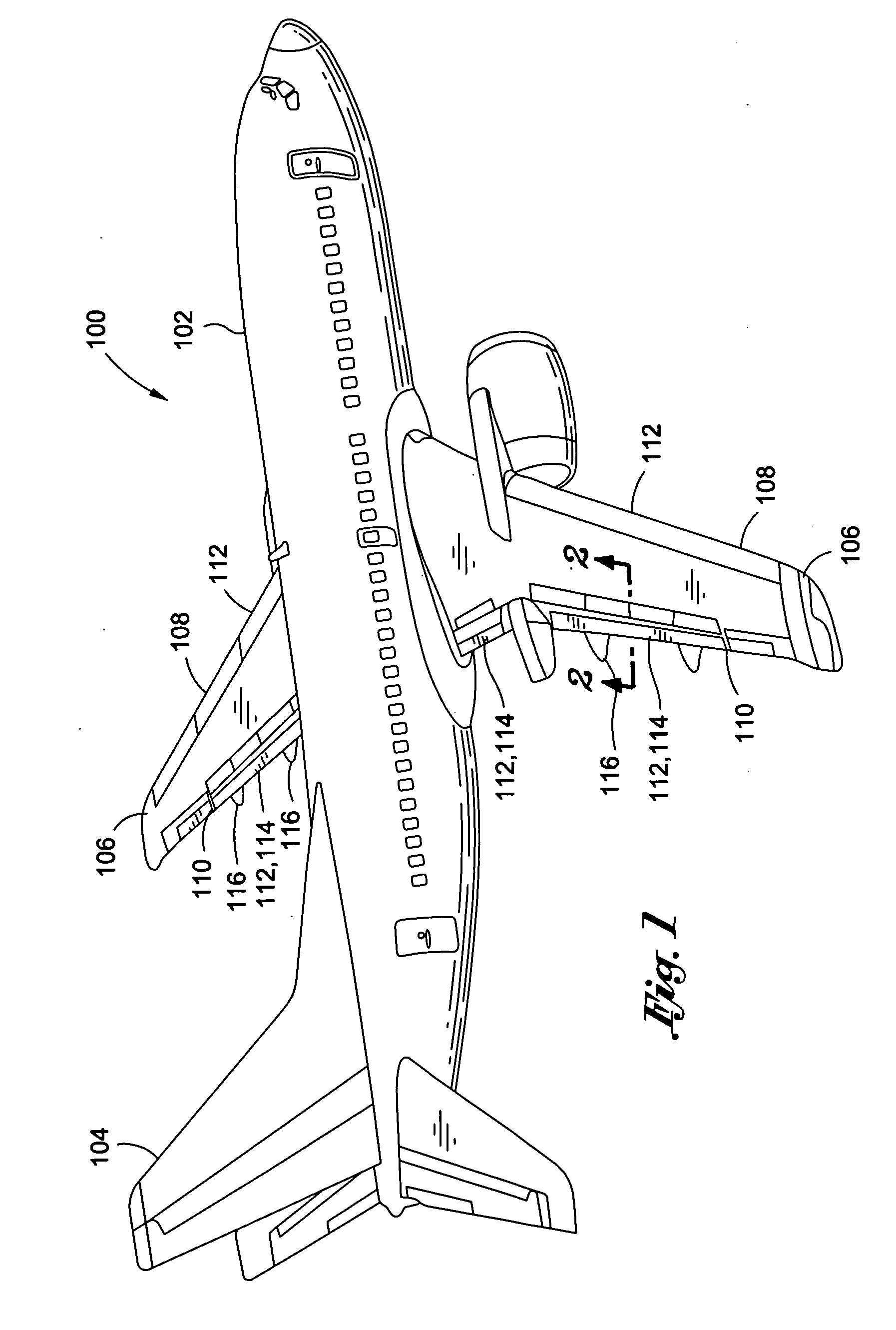
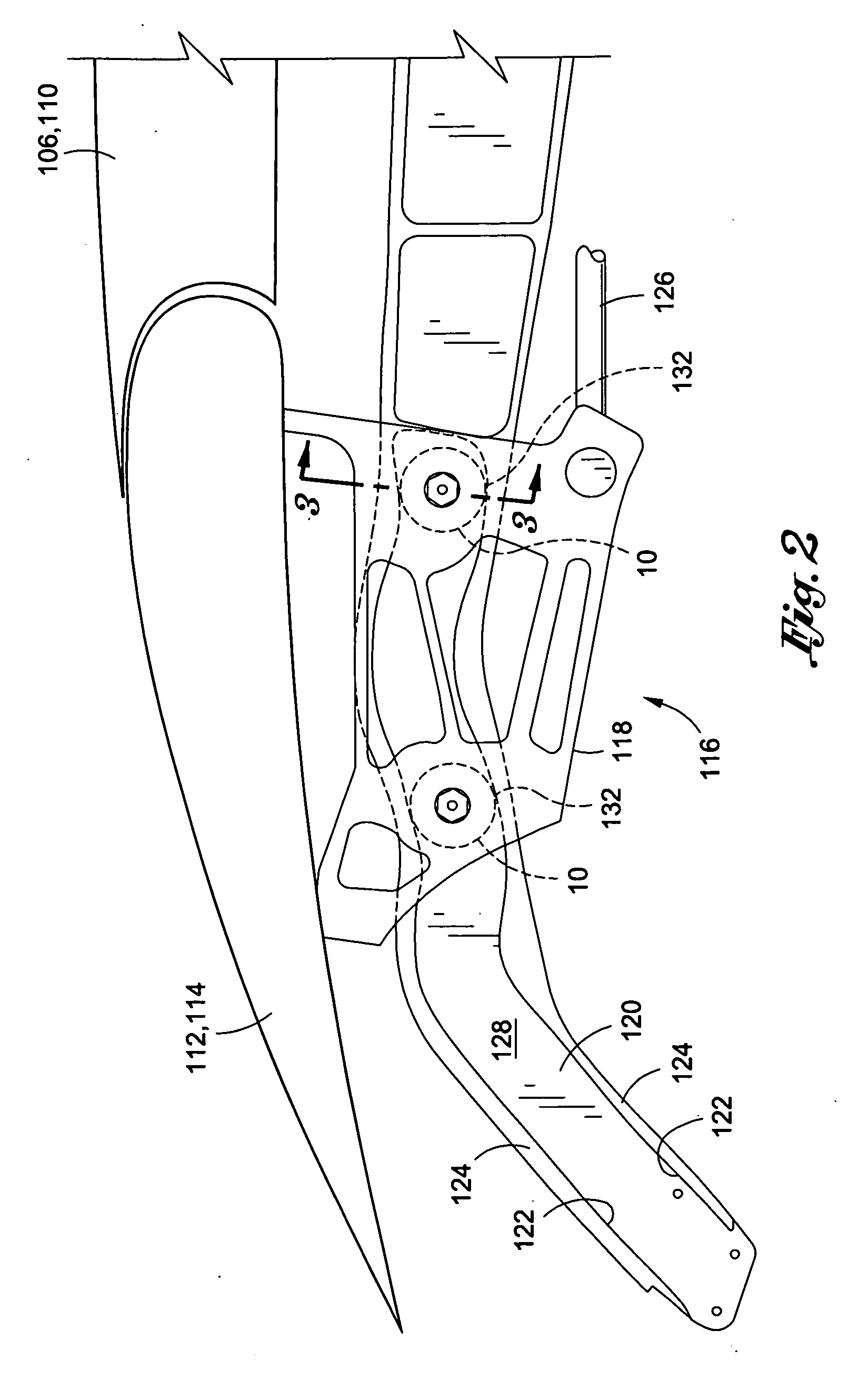
[0029]Referring now to the drawings wherein the showings are for purposes of illustrating preferred and various embodiments of the disclosure only and not for purposes of limiting the same, shown in FIG. 1 is a perspective illustration of an aircraft 100 which may employ one or more roller assemblies 10 as disclosed herein. The roller assembly 10 is adapted to reduce or prevent axial motion of an outer roller surface 52 of the roller assembly 10 relative to a track surface 122 to which the roller surface 52 may be placed in rolling contact. By reducing or eliminating axial motion of the roller surface 52 relative to the track surface 122, the service life of the track surface 122 may be increased.

[0030]Referring briefly to FIG. 4, the roller assembly 10 may include a first race 18 and a second race 20 that is coaxial with the first race 18. The second race 20 may be rotatable about a roller axis 12 relative to the first race 18. The first and second races 18, 20 comprise a race asse...


PUM

PropertyMeasurementUnit
Frictional forceaaaaaaaaaa
Displacementaaaaaaaaaa
Dynamicaaaaaaaaaa

Abstract

A roller assembly comprises a first race and a second race. The second race is coaxial with the first race and is axially movable relative to the first race. The first and second races are movable between a static axial position and a dynamic axial position relative to one another. The roller assembly includes at least one biasing member that is operative to bias the first and second races from the dynamic axial position toward the static axial position.

Description

CROSS-REFERENCE TO RELATED APPLICATIONS[0001](Not Applicable)STATEMENT RE: FEDERALLY SPONSORED RESEARCH / DEVELOPMENT[0002](Not Applicable)FIELD[0003]The present disclosure relates generally to bearing assemblies and, more particularly, to track roller bearings that are configured to increase the service life of tracks as a result of a reduction in axial motion of the roller surface relative to the track surface.BACKGROUND[0004]Many aircraft include control surfaces that may be extendable from the leading and / or trailing edges of the aircraft wings. For example, many aircraft are fitted with wing flaps that may be extended from the wing trailing edges to increase the lift capability of the wings during takeoff and landing of the aircraft. Each trailing edge wing flap may be mounted to the wing by a pair of flap track assemblies which may be located near the inboard and outboard ends of each flap. The flap may be coupled to each track assembly by a flap carriage which is movable along ...

Claims


Application Information

Patent Timeline
29 Jul 2010
Publication
US20100187367A1
IPC
B64C3/50; F16C33/58; B21D53/10; B64C1/00
CPC
B64C9/02; B64C9/16; Y10T29/53104; F16C23/082; F16C2326/43; F16C19/46
Inventors
DAHL, BRUCE A.