
Shotshell wad with shot confinement feature

a technology of shot confinement and shot shell, which is applied in the field of ammunition, can solve the problems of affecting the dispersion of ammunition payload, and the friction of the finger, and achieves the effect of tighter shot patterns

Inactive Publication Date: 2010-08-05
AMMUNITION OPERATIONS LLC
View PDF99 Cites 8 Cited by
  • Summary
  • Abstract
  • Description
  • Claims
  • Application Information

AI Technical Summary

Benefits of technology

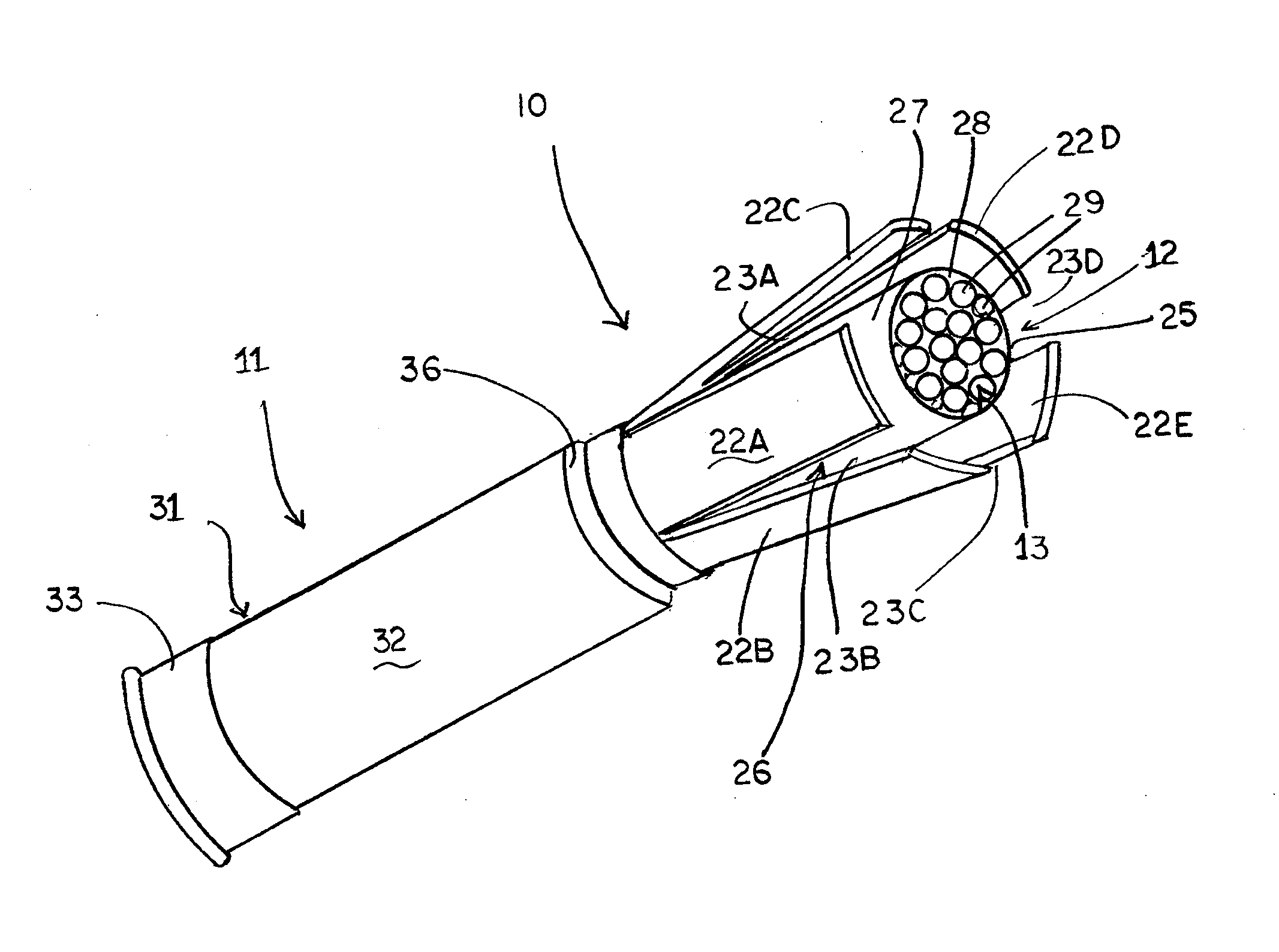
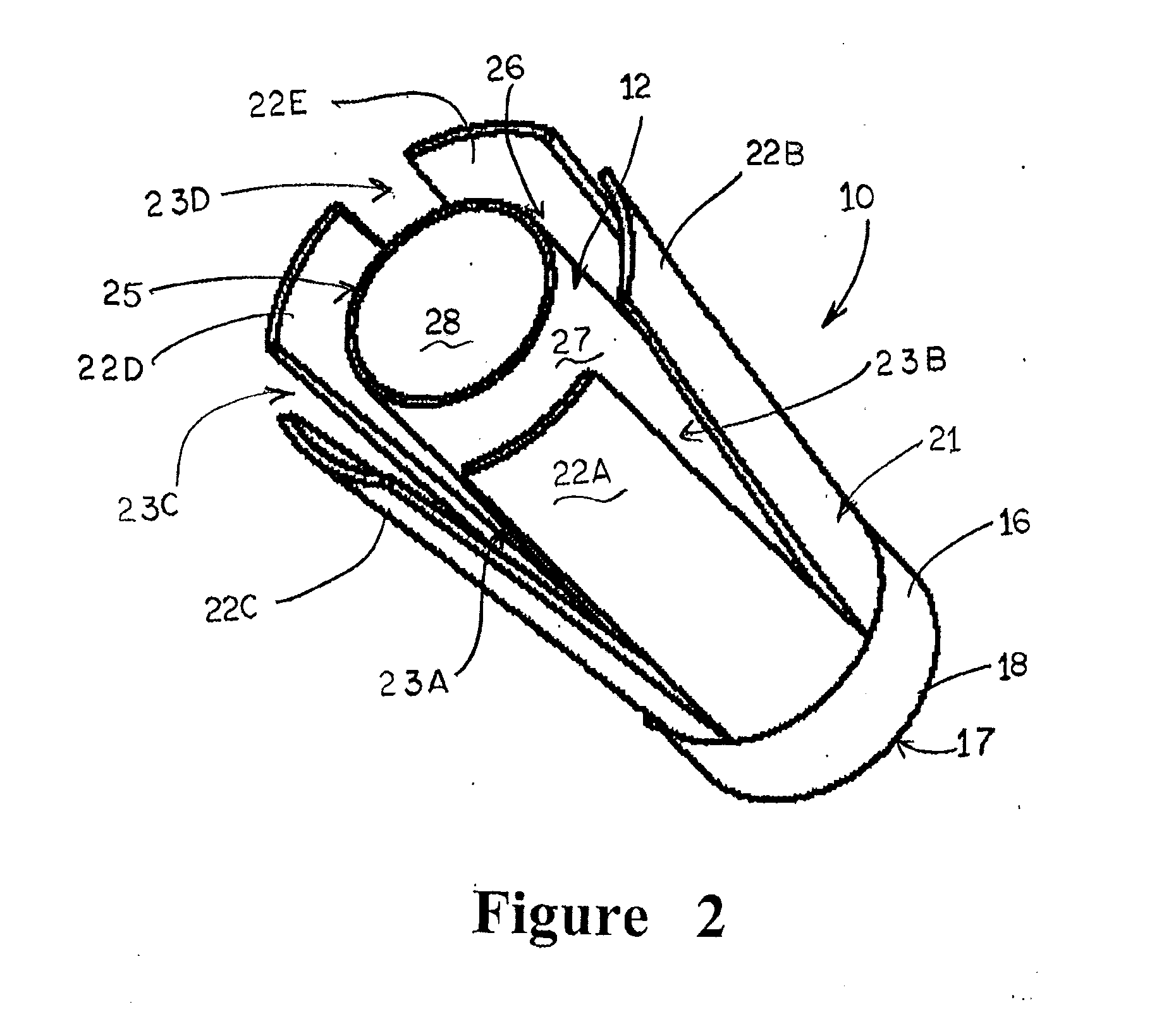
[0007]Upon firing of a shotshell or other type cartridge, the fingers of the shotshell wad will begin to separate and spread as the shotshell wad exits the barrel of the firearm. The spreading fingers encounter aerodynamic drag, which causes separation of the shotshell wad from the ammunition payload contained therein. The ammunition payload, such as a plurality of shot pellets, is contained and maintained within the confinement tube as the fingers spread and separate the shotshell wad from the ammunition payload. As a result, the ammunition payload, such as a grouping of shot pellets, generally is maintained in a conglomerated or contained mass until separation of the shotshell wad therefrom. This in turn causes a delay in the dispersion of the ammunition payload, enabling tighter shot patterns.

Problems solved by technology

The spreading fingers encounter aerodynamic drag, which causes separation of the shotshell wad from the ammunition payload contained therein.
This in turn causes a delay in the dispersion of the ammunition payload, enabling tighter shot patterns.

Method used


Image

  • Shotshell wad with shot confinement feature
  • Shotshell wad with shot confinement feature
  • Shotshell wad with shot confinement feature

Examples


Embodiment Construction

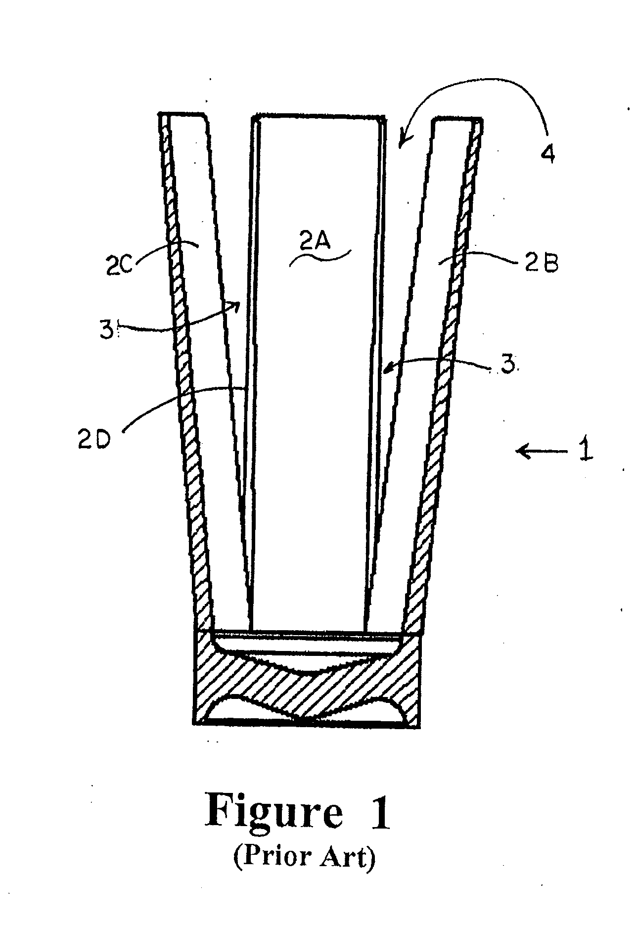
[0013]Referring now to the drawings in which like numerals indicate like parts throughout the several views, FIG. 1 generally illustrates a conventional shotshell wad design 1, such as typically used with shotshells firing steel shot. Such a wad 1 typically is made from a plastic or other synthetic material and, as is conventional, generally has a series of fingers or sections 2A-2D separated by a series of spaced cuts 3. These fingers, when the wad is inserted into the shotshell, are designed to close together to form a cup 4 in which the shot payload is contained within the shotshell. This cup travels with the payload of shot as the shot travels down the barrel of a firearm after firing of the shotshell until the point at which the shot and cup separate from the barrel of the firearm at the muzzle thereof.

[0014]As the shot payload and wad 1 exit the muzzle of the firearm, the fingers 2A-2D of the wad generally are caused to flare outwardly due to wind resistance against the finger...


PUM


Abstract

A wad for ammunition cartridges, including shotshell cartridges, includes a wad body having a series of separable fingers. A shot confinement tube is located within the wad body, surrounded by the separable fingers. The confinement tube extends longitudinally along the wad body and defines a recess in which an ammunition payload is received and is contained upon firing of the ammunition cartridge and as the wad is separated from the ammunition payload.

Description

CROSS-REFERENCE TO RELATED APPLICATIONS[0001]The present patent application is a formalization of previously filed, co-pending U.S. Provisional Patent Application Ser. No. 61 / 149,059, filed Feb. 2, 2008, entitled “Shot Confinement Wad” by the inventors named in the present Application. This patent application claims the benefit of the filing date of this cited Provisional patent application according to the statutes and rules governing provisional patent applications, particularly 35 U.S.C. §119(a)(i) and 37 C.F.R. §1.78(a)(4) and (a)(5). The specification and drawings of the Provisional patent application referenced above are specifically incorporated herein by reference as if set forth in their entirety.FIELD OF THE INVENTION[0002]The present invention generally relates to ammunition such as shotshells, and in particular to a shotshell wad design having a confinement feature for controlling dispersion of the ammunition payload of a shotshell after firing.BACKGROUND OF THE INVENTIO...

Claims


Application Information

Patent Timeline
IPC IPC(8): F42B7/08
CPCF42B7/08
Inventor CROSS, KEVIN R.
Owner AMMUNITION OPERATIONS LLC
Learn More