Shot cup wad

a technology of shot shell and wad, which is applied in the field of shot shells, can solve the problems of inconsistent and unpredictable placement of shot patterns, veering or directing shot shell wads, and adverse effects on shot patterns, and achieves the effects of facilitating a substantially rapid separation, enhancing the ability of shot pellets, and speeding up the wad

Active Publication Date: 2015-06-25
AMMUNITION OPERATIONS LLC
View PDF6 Cites 9 Cited by
  • Summary
  • Abstract
  • Description
  • Claims
  • Application Information

AI Technical Summary

Benefits of technology

[0006]Upon firing, a primer blast is directed into the rear cylinder so as to ignite the propellant powder, which produces pressurized gas. The pressurized gas will expand within the rear cylinder so as to propel the wad and the payload received in the forward cylinder down a firearm barrel. Once the wad exits the muzzle end of the barrel, the pressurized gas acting on the rear cylinder can cause rupturing of the rear cylinder at the impressions to form a series of petals, which petals can flare outwardly (e.g., radially) from the rear cylinder in response to the pressure from the propellant gases. In one embodiment, heat from combustion of the propellant can aid in the rupture of the rear cylinder along the impressions for formation of the petals. The deployed petals can rapidly slow the wad to provide and / or facilitate a substantially rapid separation between the wad and the shot pellets, which exit the forward end of the forward cylinder. This can foster enhanced ability of the shot pellets to stay on target during and after release from the wad and can provide a tighter shot pattern since the shot payload remains in a generally cylindrical shape for a longer period of time and the separation is more likely to occur before instabilities develop in the wad after exiting the firearm barrel.
[0007]In another embodiment, an un-slit or substantially un-perforated wad or shot cup for holding shot in a shotshell cartridge or other round of ammunition is disclosed. The shot cup can be formed with a one-piece or substantially unitary body structure that includes a first cylindrical forward portion for receiving shot pellets, and a shorter second cylindrical rear portion adjacent a charge of propellant. The forward portion and the rear portion can be joined at a common intermediate partition. The sidewall of the rear portion further can include one or more molded impressions within its interior. The shapes of the impressions can help form the contoured depressions or other features defining one or more spaced apart, unformed (latent) deceleration features wherein the greatest depth of each contoured depression forms a thin web of rupturable shot cup material. When the shotshell cartridge is fired, the cylindrical rear portion of the shot cup can be heated by hot propellant gases sufficient to soften and cause radially stretching of the web areas, weakening and preconditioning such web areas as the shot cup traverses a forcing cone area of the shotgun barrel. As the shot cup exits the muzzle of the shotgun barrel, the high pressure expanding gases can substantially instantly or otherwise rapidly rupture the contoured web areas, causing deceleration features to form in and subsequently deploy from the shot cup body in an outward radial direction. Sudden deployment of the deceleration features combined with redirected gas jets can help create a powerful deceleration impulse by way of increased air resistance. Such air resistance can cause the shot cup to become separated or strip away from the shot column in a substantially straight path or action that facilitates / causes a substantially dense and centered downrange pellet pattern of smaller or reduced diameter. After the shot cup is fired, the material at the mouth area of the cylindrical rear portion further can remain substantially undivided and intact.

Problems solved by technology

However, such air pressure can have an adverse effect on the shot pattern since the incoming air pressure and / or flow can cause radial spreading of the forward petals and disperse shot pellets in a wider-than-desired pattern too quickly.
Uneven deployment of the petals (e.g., due to the uneven air pressure within the shot cup of the shotshell wad as the air passes through the unevenly dispersed shot pellets in the shot cup) can cause the shotshell wad to veer or be directed away from the intended direction of the shot.
This can affect the trajectory of some or all of the shot pellets and can inconsistently spread out and increase the width of the shot pattern, subsequently resulting in inconsistent and unpredictable placement of the shot pattern from shot to shot.

Method used


Image

  • Shot cup wad
  • Shot cup wad
  • Shot cup wad

Examples


first embodiment

[0072]FIGS. 16A-16D are general detail views showing variations on the contoured depressions 345 (FIG. 15C) with various redirector features 352a, 352b, 352c, 352d formed in the end of respective legs 344a, 344b, 344c, 344d of the respective contoured depressions 345a, 345b 345c, 345d. The legs 344a, 344b, 344c, 344d further can have respective alternative shapes with respect to the straight legs 144 shown in FIGS. 2-7 of the Broken arrows 309a, 309b 309c, 309d show an example of a final or end direction of the tearing forces and an example of the extent they can be redirected relative to the rearward end 125 of the shot cup according to exemplary embodiments, though other directions of such forces and tearing also can be provided.

[0073]FIGS. 16A-16C illustrate respective examples of embodiments of the contoured depressions formed in the interior surface of the rear portion of the shot cup. FIG. 16D is a partial side view of the exterior surface of a shot cup showing the contoured ...

sixth embodiment

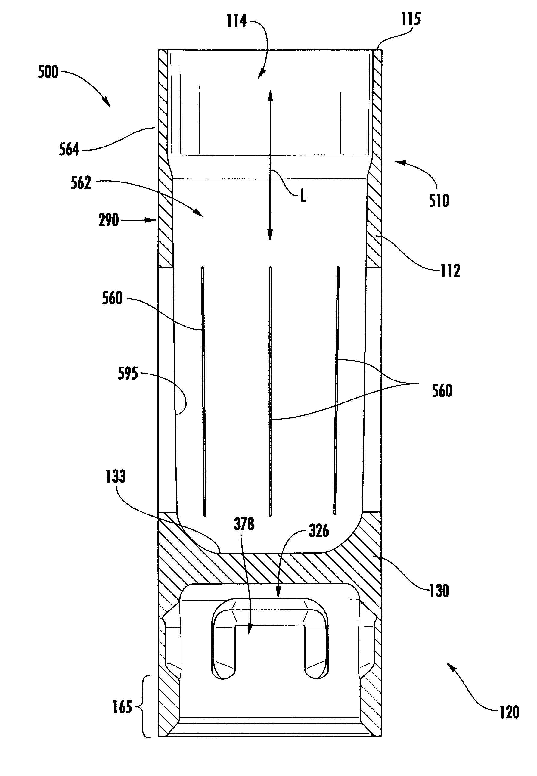
[0086]FIGS. 21A-21C illustrate a wad or shot cup 600 according to the disclosure. Shot cup 600 can have a structure that is generally similar to one or more of the embodiments discussed above, except for variations noted and variations that will be apparent to one of ordinary skill in the art. Accordingly, similar or identical features of the embodiments have been given like or similar reference numbers in most of the drawing figures. As shown in FIG. 20A, the shot cup 600 includes several V-shaped, longitudinal indentions (essentially, angular valleys) 680 formed in the outer surface 690 of the forward cylindrical portion 610. Each of the longitudinal indentations 680 can include a respective longitudinal slot 660. The longitudinal indentations 680 and the associated longitudinal slots 660 can be arranged in a series 662 in a slit region D4 and can be spaced apart from the forward end 115 of the shot cup 600 by the distance D3. Accordingly, the un-slit portion 564 can extend betwee...


PUM


Abstract

A wad or shot cup having a forward cylinder portion receiving a payload and a rear cylinder portion receiving a charge of propellant. One or more latent deceleration features can be formed in a surface of the sidewall extending along the rear cylinder portion. The latent deceleration features can be spaced apart from a rearward end of the shot cup and can be deployed to form deceleration petals after the shot cup is fired from a firearm. A series of longitudinal slits can be formed in the forward cylinder portion so that a portion of the sidewall expands radially adjacent the longitudinal slits after the shot cup is fired from a firearm for urging at least a portion of the payload to exit the forward cylinder portion.

Description

CROSS REFERENCE TO RELATED APPLICATIONS[0001]The present patent application is a formalization of previously filed, co-pending U.S. Provisional Patent Application Ser. No. 61 / 919,031, filed Dec. 20, 2013, by the inventors named in the present Application. This patent application claims the benefit of the filing date of the United States Provisional patent application cited above according to the statutes and rules governing provisional patent applications, particularly 35 U.S.C. §119(e) and 37 C.F.R. §1.78(a)(3)-(4). The specification and drawings of the United States Provisional patent application referenced above are specifically incorporated herein by reference as if set forth in their entireties.FIELD OF THE INVENTION[0002]The present invention generally relates to shotshells with other applications related to ammunition products and / or systems for delivery / firing of a projectile. In particular, the present invention relates to improvements in shot cups and / or wads for shotshell...

Claims


Application Information

Patent Timeline
Patent Type & Authority Applications(United States)
IPC IPC(8): F42B7/08F42B7/04
CPCF42B7/04F42B7/08F42B7/043
Inventor BURCZYNSKI, THOMAS J.LANGENFELD, JONATHAN W.
Owner AMMUNITION OPERATIONS LLC
Why Eureka
Try Eureka