
Component transfer apparatus and method

a technology of component transfer and rack, applied in the direction of electrical equipment, loading/unloading, storage devices, etc., can solve the problems of reducing a production efficiency, affecting the efficiency of the whole production line, so as to reduce the cost of configuration, simplify the operation, and minimize the effect of equipmen

Active Publication Date: 2010-08-05
HIRATA & CO LTD
View PDF27 Cites 2 Cited by
  • Summary
  • Abstract
  • Description
  • Claims
  • Application Information

AI Technical Summary

Benefits of technology

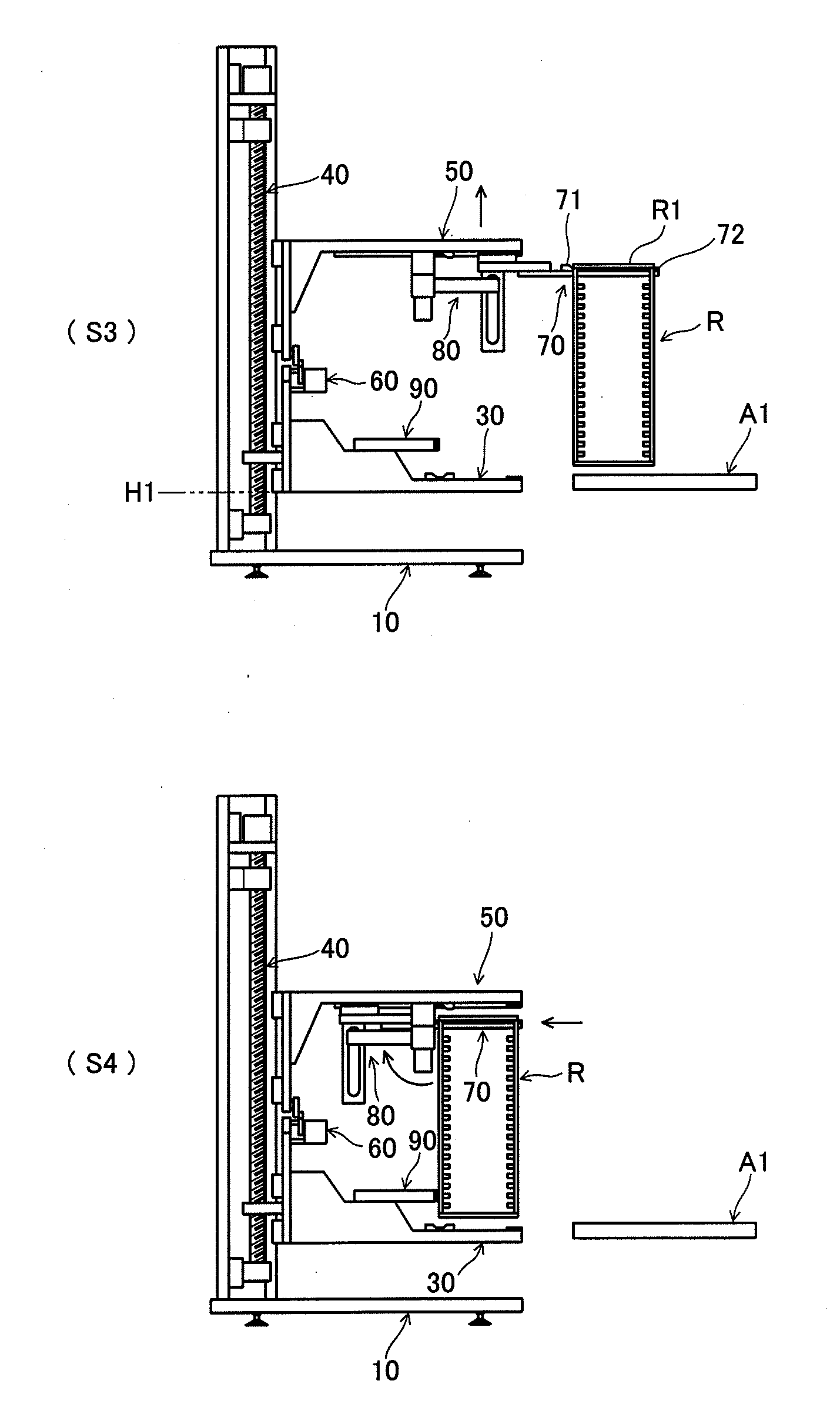
[0040]The component transfer apparatus and method having the above-described configuration can flexibly cope with various kinds of racks (or magazines or cassettes) utilized when supplying and retrieving components, and can smoothly and highly accurately perform transfer and positioning each rack while achieving, e.g., simplification, miniaturization, or cost reduction of the configuration, and thereby smoothly supplying and retrieving the components, and improving operation efficiency and productivity.

Problems solved by technology

Further, there are racks having various conformations, e.g., one having high rigidity or low rigidity, one distorted due to use over the years, and others.
Therefore, when such a rack is transferred to a predetermined position to simply perform component supplying and retrieving operations without being assuredly positioned, these operations may not be smoothly performed and a fetch failure or a retrieval failure may possibly occur, thereby eventually affecting an entire production line using the components to lower a production efficiency.
Furthermore, since the magazine is moved while being dragged along a support surface when transferring the magazine between the magazine supply stage and the elevator, if there is a step between the magazine supply stage and the elevator, the magazine may be caught on this step or may receive an impact when getting over the step, whereby an untransferable state may occur or an accommodated component may possibly fall or may be damaged.
Therefore, double facilities, managements and costs are required to supply these two types of energy.
However, this apparatus individually requires a driving mechanism (e.g., a cylinder) that pushes the frame from the vertical direction and a driving mechanism (e.g., a cylinder) that pushes the frame from the lateral direction, thereby leading to complication of a configuration, an increase in cost, and others.
Further, the rack carried into the frame can be set out at the predetermined position in the frame, and the rack can be moved up and down, but the rack cannot be carried into the frame or carried out from the frame by using this apparatus, whereby a dedicated transfer apparatus that transfers the rack is required.
Therefore, double facilities, managements and costs are required to supply these two types of energy.

Method used


Image

  • Component transfer apparatus and method
  • Component transfer apparatus and method
  • Component transfer apparatus and method

Examples


Embodiment Construction

[0100]The best mode for carrying out the present invention will now be described hereinafter with reference to the accompanying drawings.

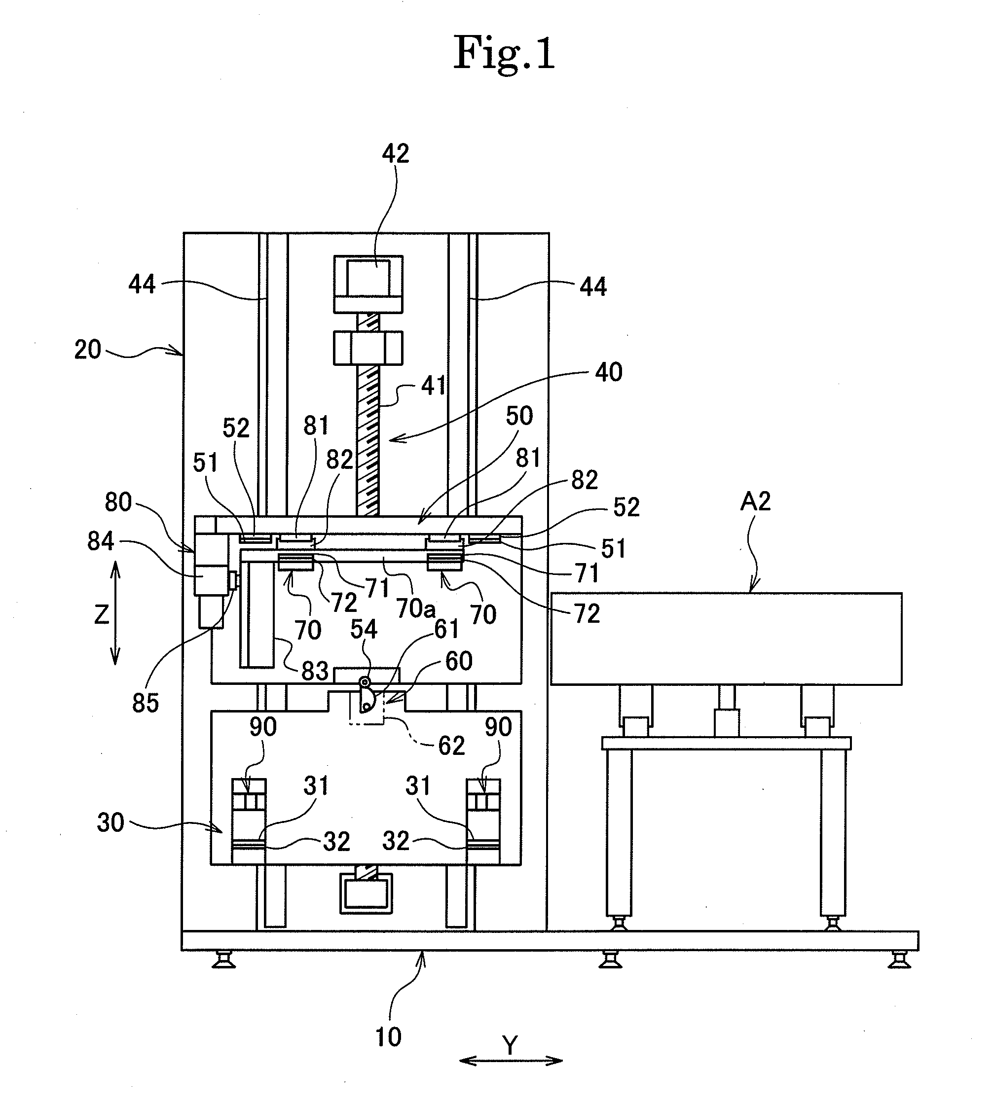
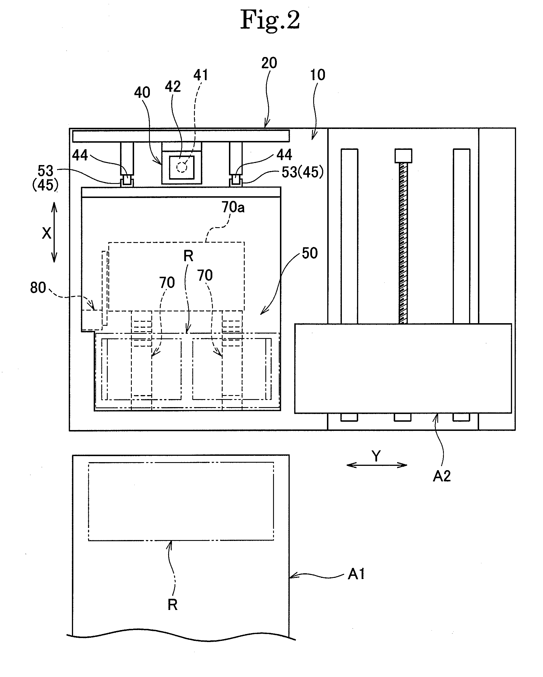
[0101]As shown in FIGS. 1 to 3, this component transfer apparatus includes a base 10, a support member 20 provided to stand upright on the base 10, a mounting member 30 on which a rack R can be mounted and which is provided to be capable of moving up and down in a vertical direction Z, a first elevation driving mechanism 40 that drives the mounting member 30 to move up and down, an upper push member 50 provided to be capable of moving up and down in the vertical direction Z in an upper area where it faces the mounting portion 30, a second elevation driving mechanism 60 that drives the upper push member 50 to move up and down, carrying hands 70 provided to be capable of reciprocating in a horizontal direction X with respect to the upper push member 50, a horizontal driving mechanism 80 that drives the carrying hands 70 to reciprocate in the horizont...


PUM


Abstract

A component transfer apparatus and method according to the present invention includes: a mounting member (30) on which a lower frame (R1) of a rack can be mounted and which is driven to move up and down in order to take out or retrieve components from the rack (R) in which the components can be aligned and accommodated in a vertical direction; an upper push member (50) that is arranged to face the mounting member from above and driven to move up and down in order to push the upper frame (R1) of the rack from above; and a carrying hand (70) that can reciprocate between a retracted position where it faces the upper push member from below and a protruding position where it protrudes from the upper push member in a horizontal direction and that is driven to move up and down so as to enter a space below the upper frame to carry and suspend the rack at the protruding position and so as to move down the rack onto the mounting member at the retracted position. As a result, the rack can be smoothly carried in or carried out and the components can be smoothly supplied and retrieved, whereby operation efficiency can be enhanced and productivity can be improved.

Description

TECHNICAL FIELD[0001]The present invention relates to a component transfer apparatus and method that set out a rack (or a magazine or a cassette) accommodating a component at a predetermined position and take out the component accommodated in the rack to be supplied to a supply area or retrieve (or collect) the component to be accommodated in the rack, and more particularly to a component transfer apparatus and method that can carry in a rack to a predetermined position to be positioned or carry out the rack from the predetermined position in order to supply or retrieve a plate-like component such as a substrate.BACKGROUND ART[0002]A rack (including, e.g., a magazine or a cassette) in which components for an electronic device or a machine are vertically aligned and accommodated has a slight error in dimension in accordance with each manufacturer even though it is applied to the same field. Further, there are racks having various conformations, e.g., one having high rigidity or low r...

Claims


Application Information

Patent Timeline
Patent Type & Authority Applications(United States)
IPC IPC(8): B65G65/00B65G1/00
CPCH01L21/6732H01L21/67778H01L21/67766H01L21/6734B65G1/0414H01L21/67712H01L21/67721H01L21/67769H05K13/021
Inventor TACHIBANA, KATSUYOSHISHINOZAKI, YOJITATENO, SOICHI
Owner HIRATA & CO LTD
Learn More