Switch device

a technology of a switch and a switch body, which is applied in the direction of contact mechanisms, contact vibration/shock damping, electrical equipment, etc., can solve the problem of noise of hitting sound, and achieve the effect of reducing the noise of hitting sound, and reducing the generated hitting sound

Inactive Publication Date: 2010-09-02
OMRON AUTOMOTIVE ELECTRONICS CO LTD
View PDF1 Cites 9 Cited by
  • Summary
  • Abstract
  • Description
  • Claims
  • Application Information

AI Technical Summary

Benefits of technology

[0006]As described above, in the conventional switch device disclosed in Japanese Unexamined Utility Model Publication Nos. 5-36721 and 2-87339, a hitting point between components that hit each other in manipulating the manipulation knob concentrates on one point, and a buffer member is provided in the hitting point. One or more embodiments of the present invention disperses the hitting point to reduce the hitting sound in manipulating the switch device.
[0008]Accordingly, the hitting impact generated between the manipulation knob and the tubular portion in manipulating the manipulation knob does not concentrate on one point, but the hitting impact is absorbed while being dispersed into the first and second hitting portions and hit portions, so that the generated hitting sound can be reduced. Since the second hit portion is provided so as to be separated from the tubular portion, a deformation amount of each surface of the tubular portion decreases when the first and second hitting portions hit the first and second hit portions by the manipulation of the manipulation knob. Therefore, the resounding hitting sound caused by the deformation can be reduced. Since the first hitting portion hits the first hit portion after the second hitting portion hits the second hit portion, the timings in which the hitting sounds are generated are temporally shifted from each other, and therefore the hitting sound can be reduced. Moreover, at least one of the second hitting portion and the second hit portion bends to relax the hitting impact, so that the hitting sound can be reduced.
[0009]In the above switch device, an area where the second hitting portion hits the second hit portion may be smaller than an area where the first hitting portion hits the first hit portion. In this manner, the hitting sound between the second hitting portion and the second hit portion is reduced smaller than the hitting sound between the first hitting portion and the first hit portion during the swing manipulation of the manipulation knob, and the hitting sound can be reduced as a whole.
[0013]Accordingly, the hitting impact generated between the manipulation knob and the tubular portion in manipulating the manipulation knob does not concentrate on one point, but the hitting impact is absorbed while being dispersed into the first and second hitting portions and hit portions, so that the generated hitting sound can be reduced. Since the first hitting portion hits the first hit portion after the second hitting portion hits the second hit portion, the timings in which the hitting sounds are generated are temporally shifted from each other, and therefore the hitting sound can be reduced. Moreover, at least one of the second hitting portion and the second hit portion bends to relax the hitting impact, so that the hitting sound can be reduced.
[0014]According to one or more embodiments of the present invention, the hitting point between the manipulation knob and the tubular portion can be dispersed to reduce the hitting sound generated in manipulating the manipulation knob.

Problems solved by technology

A user feels discomfort to the hitting sound, and the hitting sound becomes a noise.

Method used


Image

  • Switch device
  • Switch device
  • Switch device

Examples


Embodiment Construction

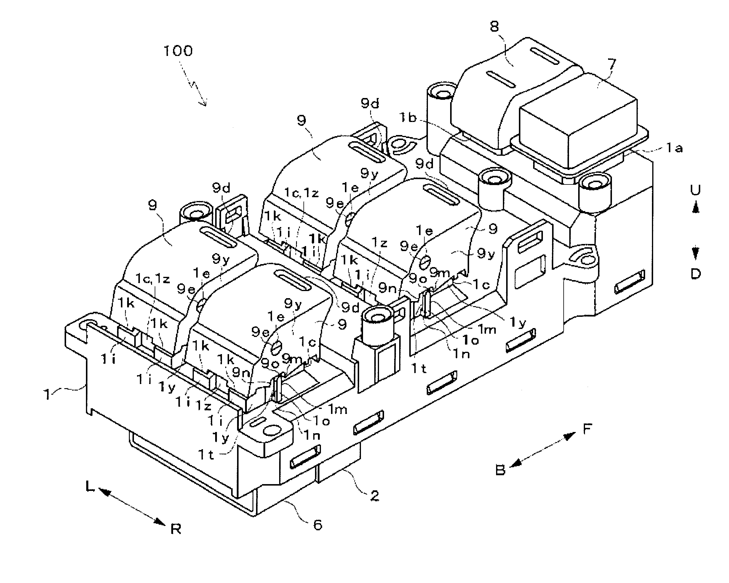
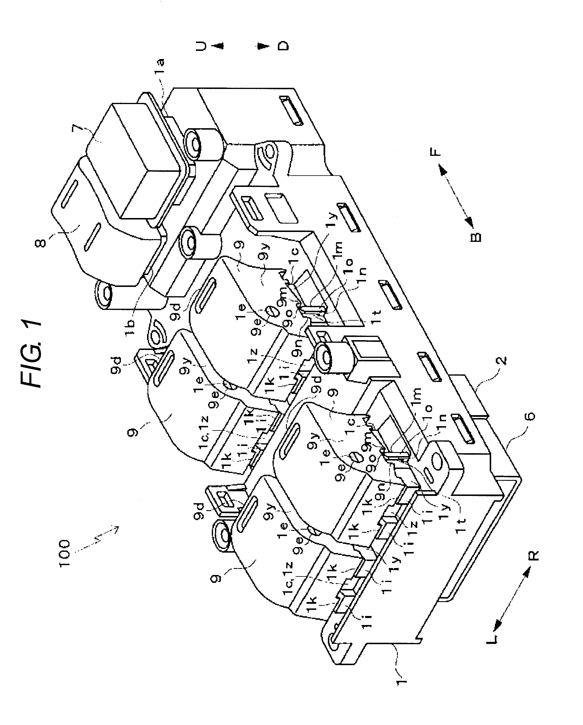
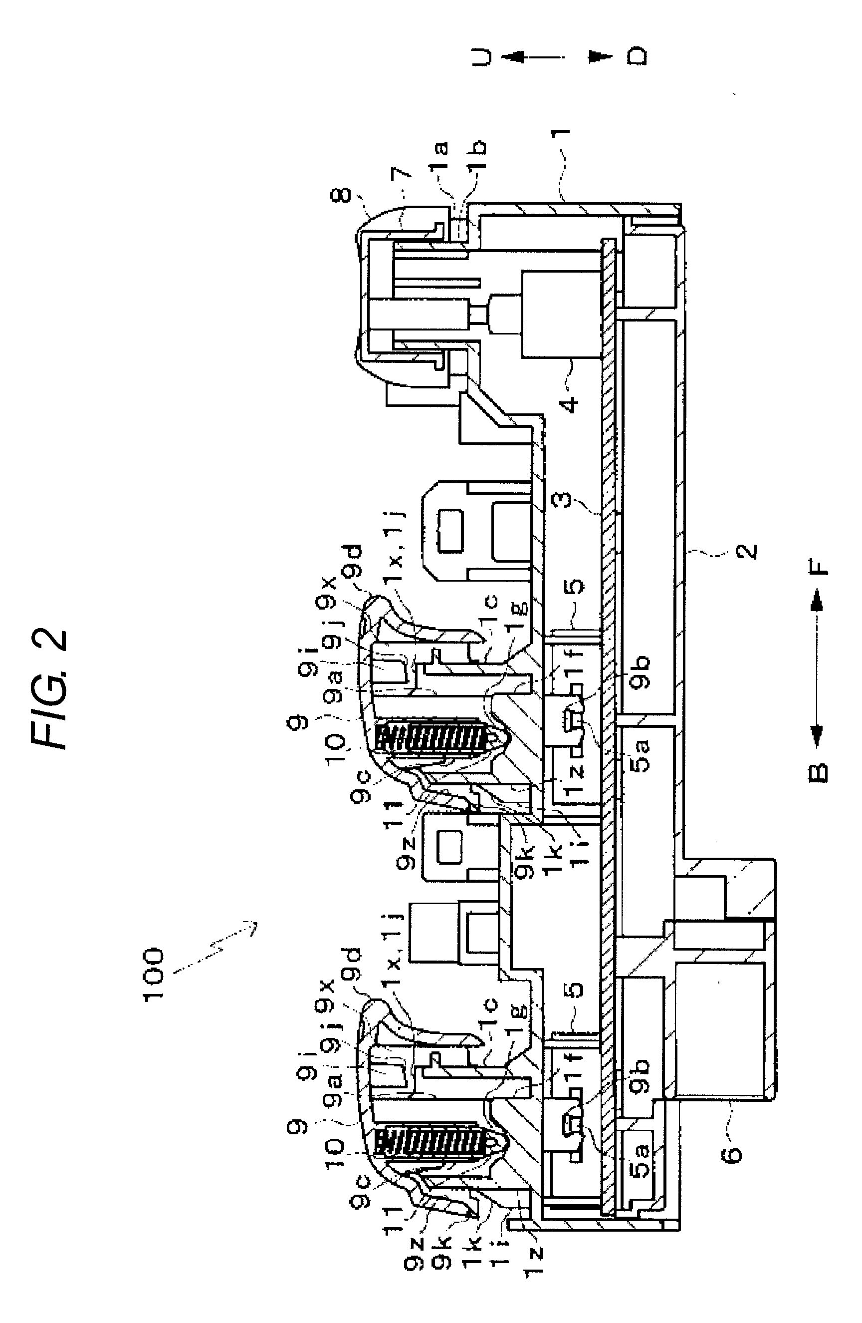
[0032]In embodiments of the invention, numerous specific details are set forth in order to provide a more thorough understanding of the invention. However, it will be apparent to one of ordinary skill in the art that the invention may be practiced without these specific details. In other instances, well-known features have not been described in detail to avoid obscuring the invention. FIG. 1 is a perspective view illustrating a switch device 100 according to an embodiment of the present invention. FIG. 2 is a sectional view of the switch device 100. The switch device 100 is used in a power window device, and the switch device 100 is mounted on an armrest (not illustrated) provided in a door of a vehicle driver seat. As illustrated in FIG. 2, a lower side (D-direction side) of a casing 1 of the switch device 100 is opened, and the lower side is closed by fitting a cover 2 therein. Electronic components such as a circuit board 3 and electric switches 4 and 5 are stored in the casing 1...


PUM


Abstract

A switch device has a casing, a tubular portion provided on the casing, an upper surface and a lower surface of the tubular portion being opened, a support shaft provided in the tubular portion, a manipulation knob attached to the tubular portion such that an opening in the upper surface is covered therewith, the manipulation knob being turned about the support shaft by manipulation, a first hitting portion provided in the manipulation knob, a first hit portion provided in the tubular portion, the first hitting portion hitting the first hit portion when the manipulation knob is turned to reach a limit of an operating range of a turning operation of the manipulation knob, a second hitting portion provided in the manipulation knob independently of the first hitting portion, and a second hit portion provided in the casing so as to be separated from the tubular portion, the second hitting portion hitting the second hit portion when the manipulation knob is turned to reach the limit of the operating range of the turning operation of the manipulation knob. ON and OFF states are switched based on the turning operation of the manipulation knob. The second hitting portion and the second hit portion are provided at positions at which the second hitting portion hits the second hit portion before the first hitting portion hits the first hit portion during the turning operation of the manipulation knob. At least one of the second hitting portion and the second hit portion bends when the second hitting portion hits the second hit portion.

Description

BACKGROUND OF THE INVENTION[0001]1. Technical Field[0002]The present invention relates to a switch device that switches ON and OFF states by manipulating a manipulation knob.[0003]2. Related Art[0004]In a switch device in which ON and OFF states are switched by manipulating a manipulation knob, constituent members of the switch device occasionally hit each other to generate a sound in manipulating the manipulation knob. A user feels discomfort to the hitting sound, and the hitting sound becomes a noise.[0005]In order to reduce the hitting sound during the manipulation, in a switch device disclosed in Japanese Unexamined Utility Model Publication No. 5-36721, a buffer member is interposed between an inner bottom surface of a cylindrical projection and a lower end-face of a sliding member, which hit each other in manipulating the manipulation knob. In a switch device disclosed in Japanese Unexamined Utility Model Publication No. 2-87339, a soft portion made of thermoplastic resin such...

Claims


Application Information

Patent Timeline
Patent Type & Authority Applications(United States)
IPC IPC(8): H01H19/14
CPCH01H3/50H01H3/60H01H2300/01H01H2021/225H01H21/22
Inventor WADA, KOTAROTOGAWA, SHINICHINISHII, MUNEKI
Owner OMRON AUTOMOTIVE ELECTRONICS CO LTD
Why Eureka
Try Eureka