
Worm gear mechanism and electric power steering apparatus equipped with the worm gear mechanism

a technology of worm gear and electric steering apparatus, which is applied in the direction of gearing, hoisting equipment, transportation and packaging, etc., can solve the problems of producing a great friction torque, and achieve the effects of enhancing the durability of the worm gear mechanism, reducing the production of sound, and avoiding backlash

Inactive Publication Date: 2010-10-19
HONDA MOTOR CO LTD
View PDF15 Cites 7 Cited by
  • Summary
  • Abstract
  • Description
  • Claims
  • Application Information

AI Technical Summary

Benefits of technology

[0013]In view of the foregoing, it is an object of the present invention to provide a technique which can reduce hitting sound between the teeth of the worm and worm wheel, which can enhance durability of the worm gear mechanism and which can maintain appropriate meshing between the worm and the worm wheel.

Problems solved by technology

Therefore, there would be produced a great friction torque.

Method used


Image

  • Worm gear mechanism and electric power steering apparatus equipped with the worm gear mechanism
  • Worm gear mechanism and electric power steering apparatus equipped with the worm gear mechanism
  • Worm gear mechanism and electric power steering apparatus equipped with the worm gear mechanism

Examples


first embodiment

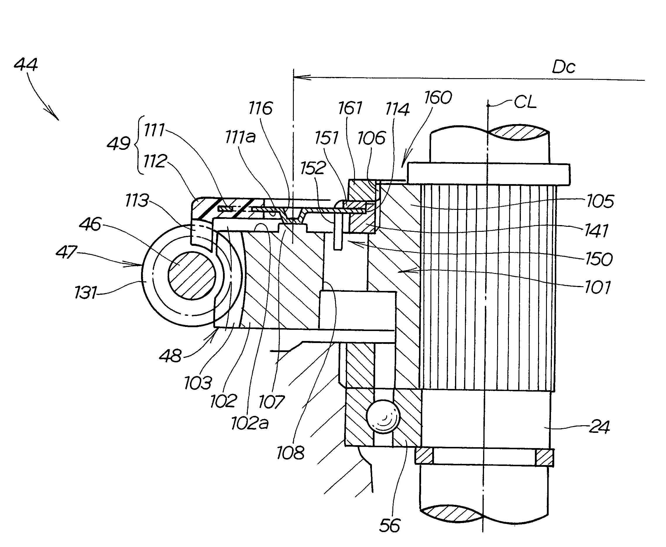
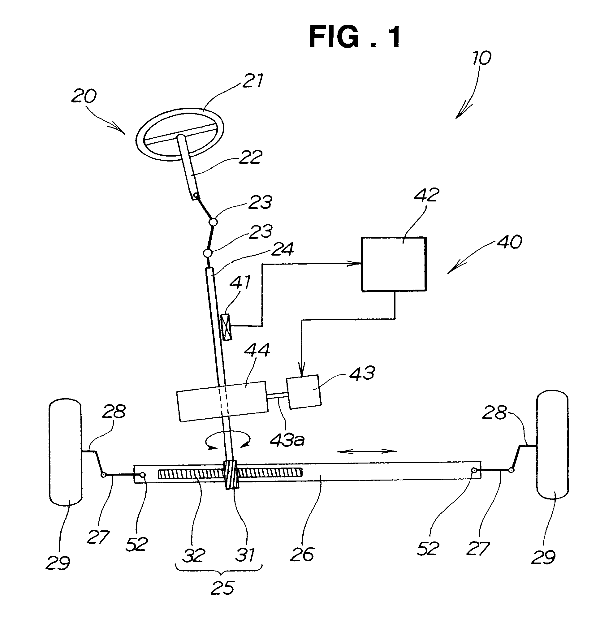
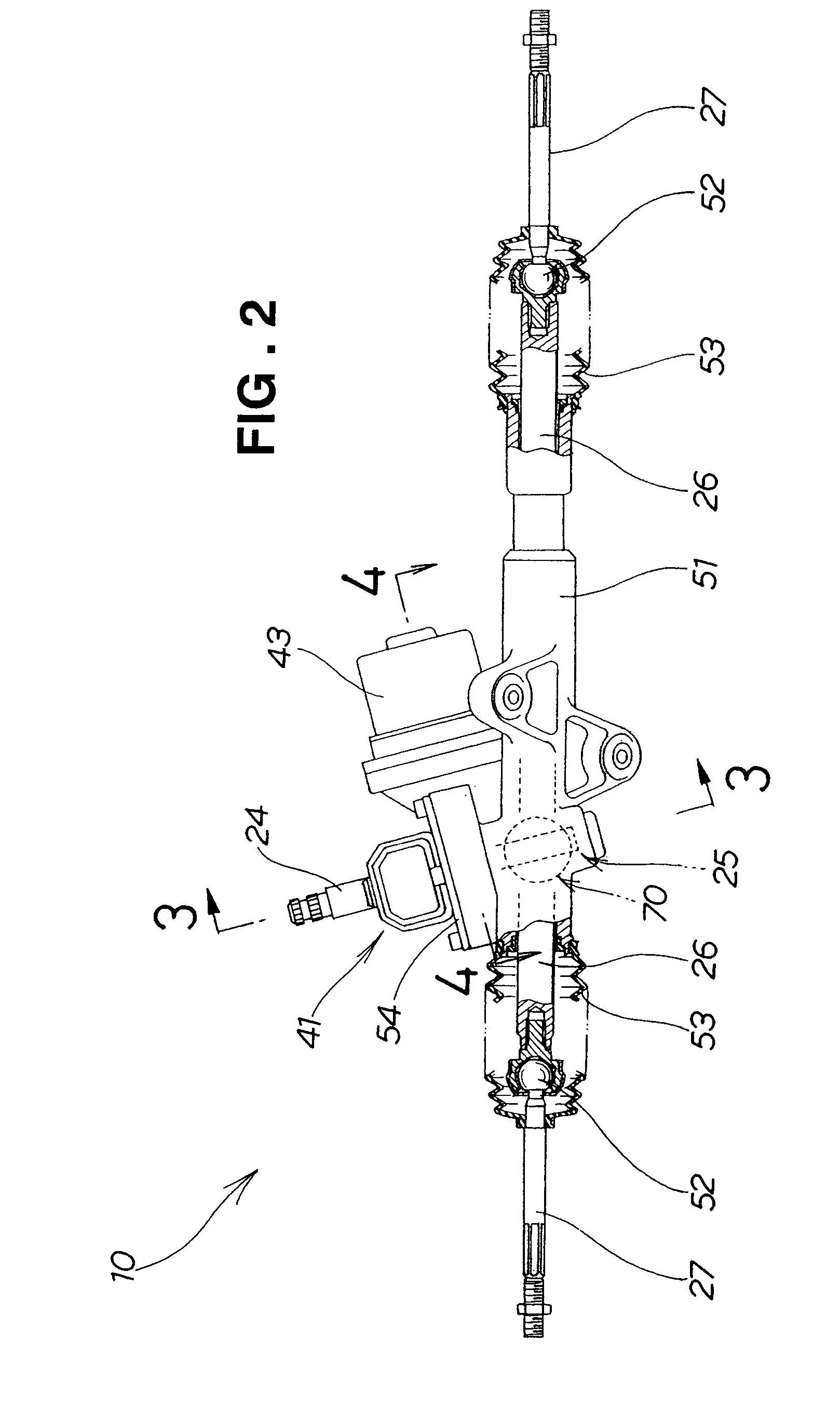
[0045]FIGS. 1 to 10 show the electric power steering apparatus and the worm gear mechanism employed in the electric power steering apparatus.

[0046]The electric power steering apparatus 10 schematically shown in FIG. 1 generally comprises a steering system 20 extending from a vehicle steering wheel 21 to steerable road wheels (in the illustrated example, left and right front road wheels) 29 of the vehicle, and a steering assist torque mechanism 40 for supplying steering assist torque to the steeling system 20.

[0047]In the steering system 20, a pinion shaft (input shaft) 24 is coupled to the steering wheel 21 via a steering shaft 22 and universal joints 23, and a rack shaft 26 is coupled to the pinion shaft 24 via a rack-and-pinion mechanism 25. Further, the left and right steerable road wheels 29 are coupled to opposite ends of the rack shaft 26 via left and right tie rods 27 and knuckle arms 28. The rack-and-pinion mechanism 25 includes a pinion 31 formed on the pinion shaft 24 and ...


PUM


Abstract

Worm gear mechanism includes a driving worm, a torque delivering worm wheel meshing with the worm, and an auxiliary worm wheel superimposed on the torque delivering worm wheel. The auxiliary worm wheel has a pitch diameter greater than that of the torque delivering worm wheel. The auxiliary worm wheel is biased against the driving worm wheel via a biasing member in the form of a leaf spring.

Description

FIELD OF THE INVENTION[0001]The present invention relates to worm gear mechanisms and electric power steering apparatus equipped with such worm gear mechanisms.BACKGROUND OF THE INVENTION[0002]The worm gear mechanisms are transmission mechanisms which include a torque delivering worm wheel meshing with a driving worm so that torque can be transmitted from the worm via the worm wheel to a load side (i.e., load-side component). In the field of such worm gear mechanisms, various techniques have been developed for reducing undesired backlashes (see, for example, Japanese Patent Application Laid-open Publication Nos. 2001-355700 and 2002-37100). The worm gear mechanism disclosed in Japanese Patent Application Laid-open Publication No. 2001-355700 is outlined in FIGS. 17A-17C, and the worm gear mechanism disclosed in Japanese Patent Application Laid-open Publication No. 2002-37100 is outlined in FIGS. 18A and 18B.[0003]FIG. 17A shows the worm gear mechanism 200 disclosed in the No. 2001-3...

Claims


Application Information

Patent Timeline
Patent Type & Authority Patents(United States)
IPC IPC(8): F16H55/18B62D5/04F16H1/16F16H55/06F16H55/24
CPCB62D5/0409Y10T74/19828Y10T74/19623
Inventor SHIMIZU, YASUOWATANABE, KATSUJIAOKI, TAKAHIROTERADA, YASUHIROTOYOFUKU, RYOJI
Owner HONDA MOTOR CO LTD
Learn More