This helps you quickly interpret patents by identifying the three key elements:
Problems solved by technology
Method used
Benefits of technology
Benefits of technology
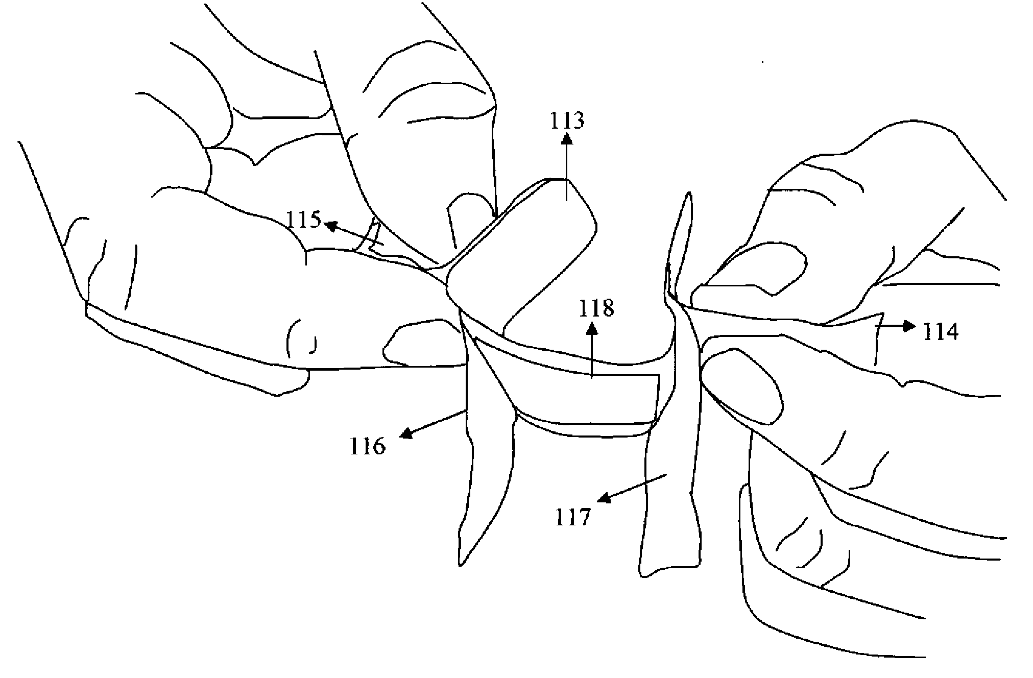
[0008]The objective of the present invention is to provide a simple, cost effective and safe mechanism for isolating the protective sterile pad of an adhesive bandage from the applicant's finger by a barrier and at the same time to isolate the applicant's fingers away from the contaminated wound. The present invention maintains the sterile environment, and preserves the sterility of the protective pad till the application is completed, and also prevents cross contamination of the wound and the applicant's finger, thereby safeguarding the user and the applicant against possible contamination and transmission of disease. Since in the preferred version the tear away tabs are substantially symmetrical, the pull is evenly distributed and the application is well controlled and precise. Further, due to the simplicity of the design, multiple gains are achieved with hardly any cost addition to existing known adhesive bandages like Band Aid™ (Johnson & Johnson). There is also described a design for the edges of the pull apart leaves of the envelope, making it easy to grasp and separate them.THE STATEMENT OF INVENTION
Problems solved by technology
There is a possibility that the uneven pull may lead to uneven application and therefore possible exposure of the wound.
On the other hand if the inner tab is pulled first then the second tear away tab may get stuck to the opposite end adhesive surface, leading to manual peeling and contamination.
Here the starting point is at one end of the adhesive bandage and away from the pad, therefore application in a controlled and precise manner may not be possible.
Method used
Image
Click on the blue label to locate the original text in one second.
Reading with bidirectional positioning of images and text.
Examples
Embodiment Construction
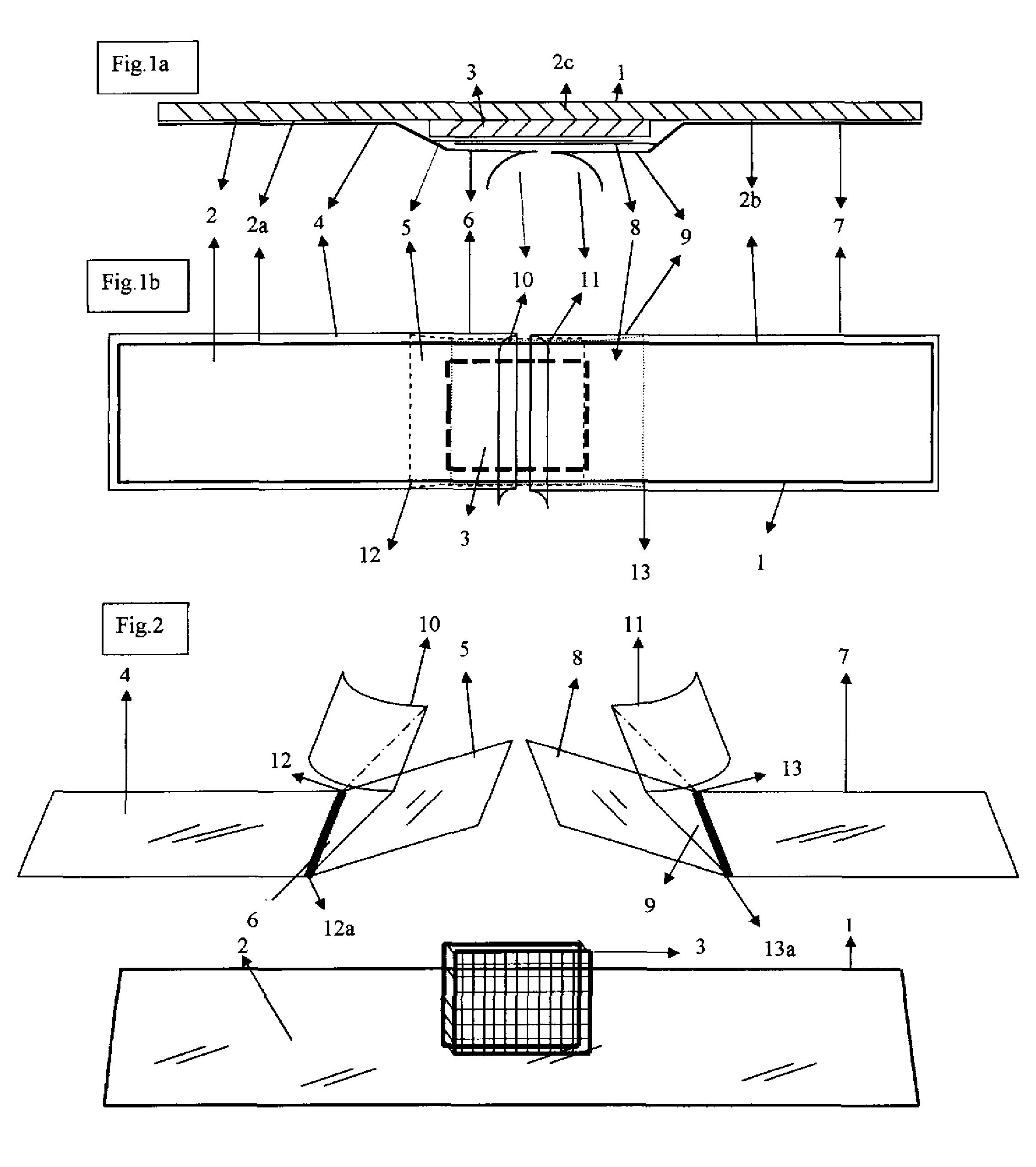
[0027]In the preferred embodiment, as shown in FIG. 1a, FIG. 1b and FIG. 2, the adhesive bandage comprises of a support 1, substantially rectangular, having one side or surface 2 adhesive with a protective sterile pad 3 which is preferably in the center of the adhesive side 2, thereby dividing the adhesive side into three parts 2a, 2b and 2c. Area 2c of the support over the pad may or may not be perforated. The adhesive support 2 itself may or may not be porous. Pad 3 is of such size that there is enough adhesive surface on all sides to seal the pad completely after application. One tear away barrier tab 4 covers adhesive surface 2a. It starts from one extremity of the support covering the surface 2b entirely towards pad 3. Close to the margin of pad 3 it becomes two layered denoted 5 and 6 and extends over the protective pad 3. The other tear away tab 7 covers adhesive surface 2b in a similar manner till near the margin of pad 3 where it becomes two layered denoted as 8 and 9 and e...
PUM
Abstract
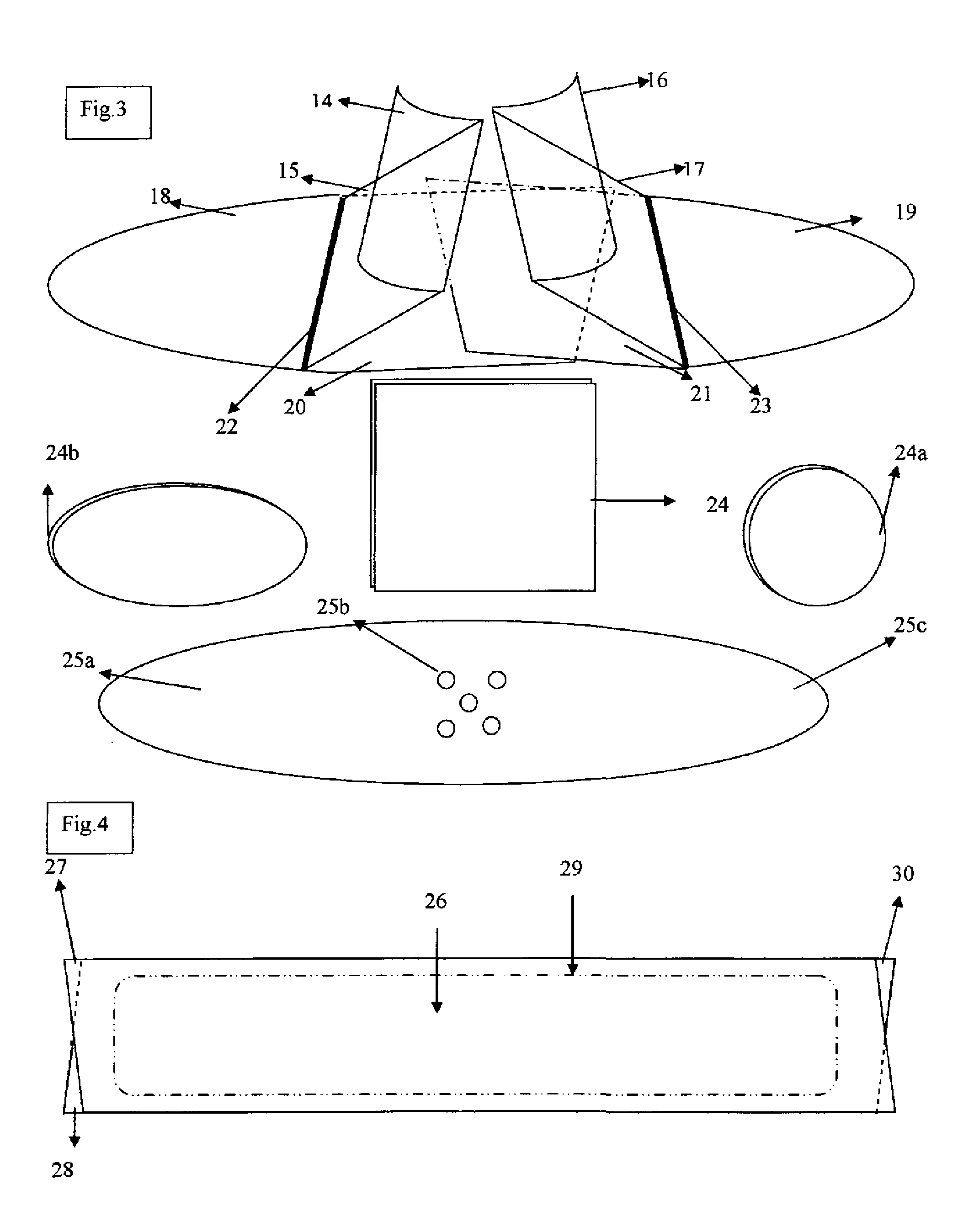
The adhesivebandage consists of a support with one surface having pressure sensitiveadhesive and a wound covering pad placed centrally on it, which are covered by two protective detachable tear away tabs. The tear away tab consists of a single layer over the adhesive surface of the support and becomes two layered over the pad region. The two layers are fused at the zone of fusion near the margin of the pad, but are otherwise free from each other. The layer close to the pad, called inner barrier layer, completely covers the pad area. The outer layer, also called grasping layer, partially covers the barrier layer and the pad, and is folded upon itself to give sufficient length. When the outer layer is grasped to pull apart the releasable tear away tabs the inner barrier layer prevents contact of the finger to the pad. As one pulls apart the tear away tabs the barrier layers unfold and prevent contact of the fingers with the wound and wound exudates, preventing cross contamination. The bandage is enclosed in an envelope with the free ends of uneven dimension to have free part of the surface of both leaves, which are easy to grasp and separate.
Application Information
Patent Timeline
Application Date:The date an application was filed.
Publication Date:The date a patent or application was officially published.
First Publication Date:The earliest publication date of a patent with the same application number.
Issue Date:Publication date of the patent grant document.
PCT Entry Date:The Entry date of PCT National Phase.
Estimated Expiry Date:The statutory expiry date of a patent right according to the Patent Law, and it is the longest term of protection that the patent right can achieve without the termination of the patent right due to other reasons(Term extension factor has been taken into account ).
Invalid Date:Actual expiry date is based on effective date or publication date of legal transaction data of invalid patent.

