
Skate cover

a technology for skates and covers, applied in the field of skate covers, can solve problems such as other limitations of related art, and achieve the effect of reducing the number of skate covers

Inactive Publication Date: 2010-09-09
IGNACIO JENNIFER YI +1
View PDF18 Cites 3 Cited by
  • Summary
  • Abstract
  • Description
  • Claims
  • Application Information

AI Technical Summary

Benefits of technology

[0026]Embodiments include a cover for an ice skate having a shoe with attached skate blade in which the cover has an exterior and an interior surface and the cover is comprised of a body and a tongue. The tongue has a slit along its length, the slit has a length which approximates the distance from the front and back blade stanchions. The body has an oval shape with a front edge and a rear edge with the tongue attached to the rear edge. The body has a left wing and a right wing, each wing has a forward edge and a rearward edge, and the left wing and right wing are permanently mated by a coupling link. The body is large enough to approximately enclose the upper and lower surfaces of the shoe. There are closers on the rearward edges of the left and right wings which are capable of reversibly connecting the left and right wings together underneath the shoe when the cover is attached to a ice skate. The cover is manufactured of flexible, elastic fabric material.

Problems solved by technology

Other limitations of the related art will become apparent to those of skill in the art upon a reading of the specification and a study of the drawings.

Method used


Image

  • Skate cover
  • Skate cover
  • Skate cover

Examples


first embodiment

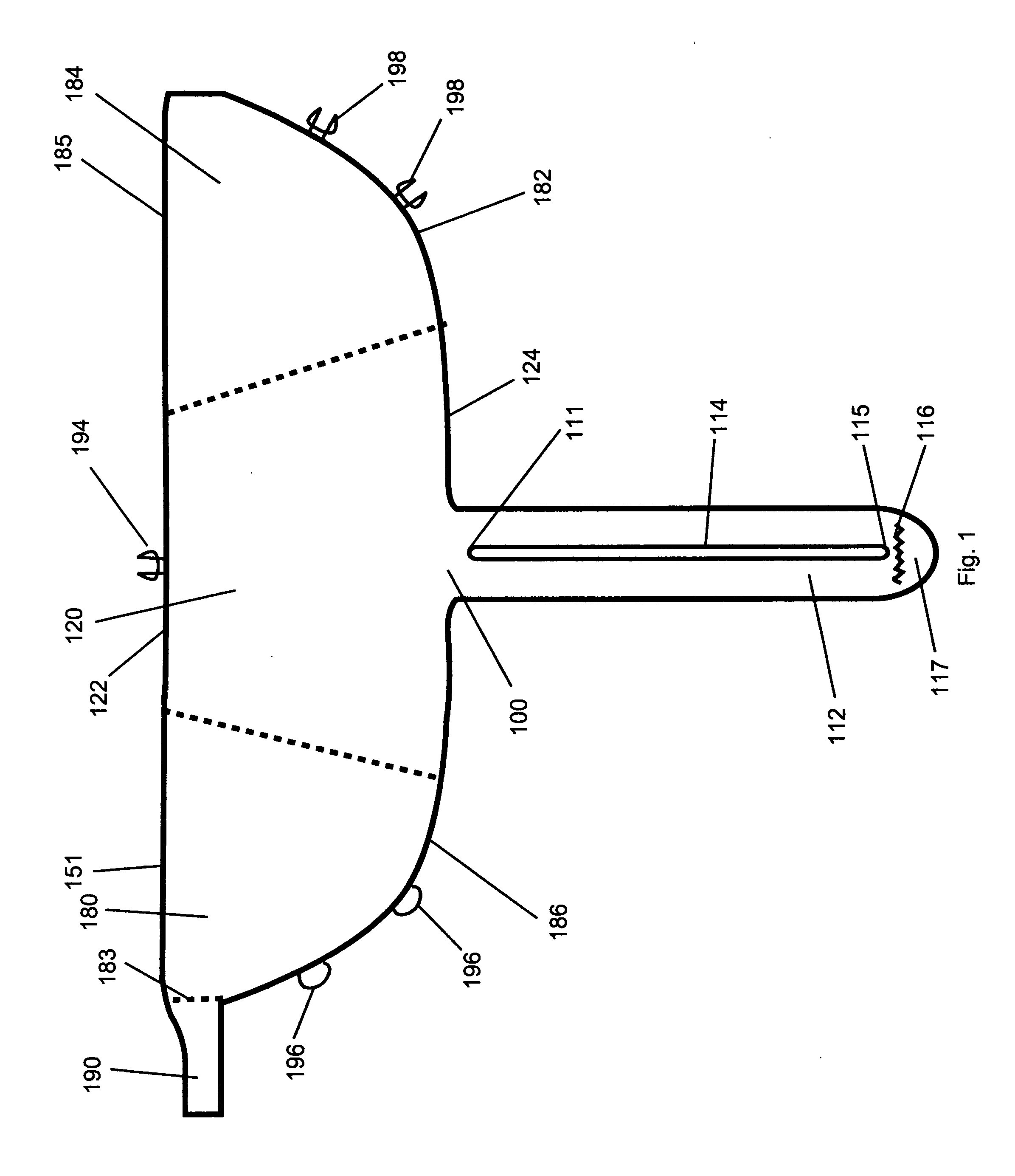
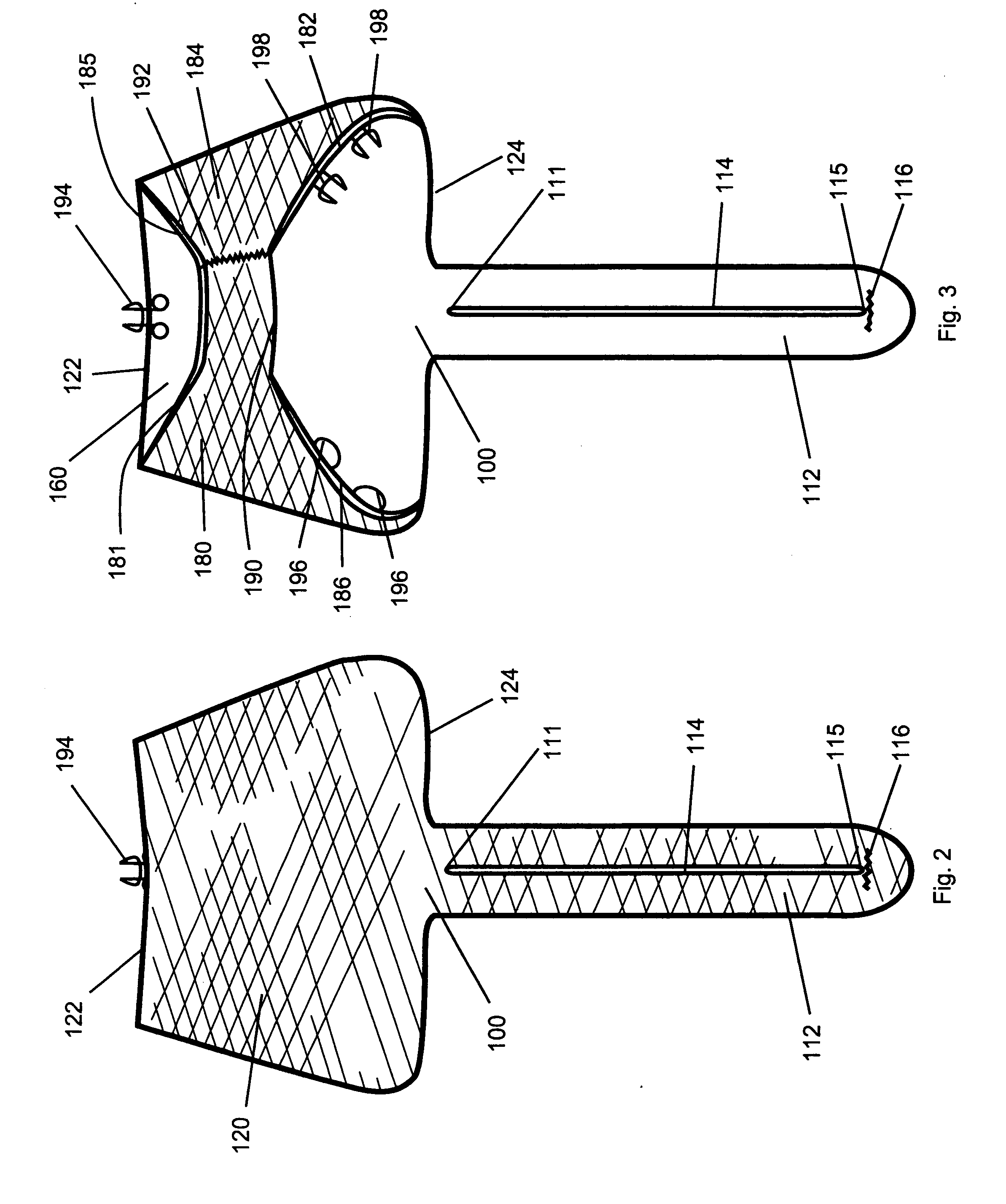
[0044]FIG. 1 is a disassembled view of the interior surface of the first embodiment skate cover without the wings mated by a coupling link. The interior surface has no particular surface treatment in all of the Figs. In all Figs. the exterior surface is indicated by cross-hatching. FIG. 1 shows the cover 100 is comprised of an oval-shaped body 120 with a front 122 edge and a rear 124 edge. A left wing 180 is located at the left edge of the body indicated by a dashed line. The left wing 180 has a front edge 181 and a rear edge 186. Attachment eyes 196 are attached to the rear edge 186. A coupling link 190 is located at the outer edge 183 of the left wing indicated by a dashed line. A right wing 184 is located at the right edge of the body indicated by a dashed line. The right wing 184 has a front edge 185 and a rear edge 182. Attachment hooks 198 are attached to the rear edge 182. A lacing hook 194 is attached to the front edge 122 of the body 120.

[0045]A tongue 112 is attached to th...

second embodiment

[0071]An embodiment of the process or method of applying an embodiment cover to a ice skate is further illustrated by FIGS. 9-14. A similar method is used to apply a second embodiment cover to an in-line roller skate.

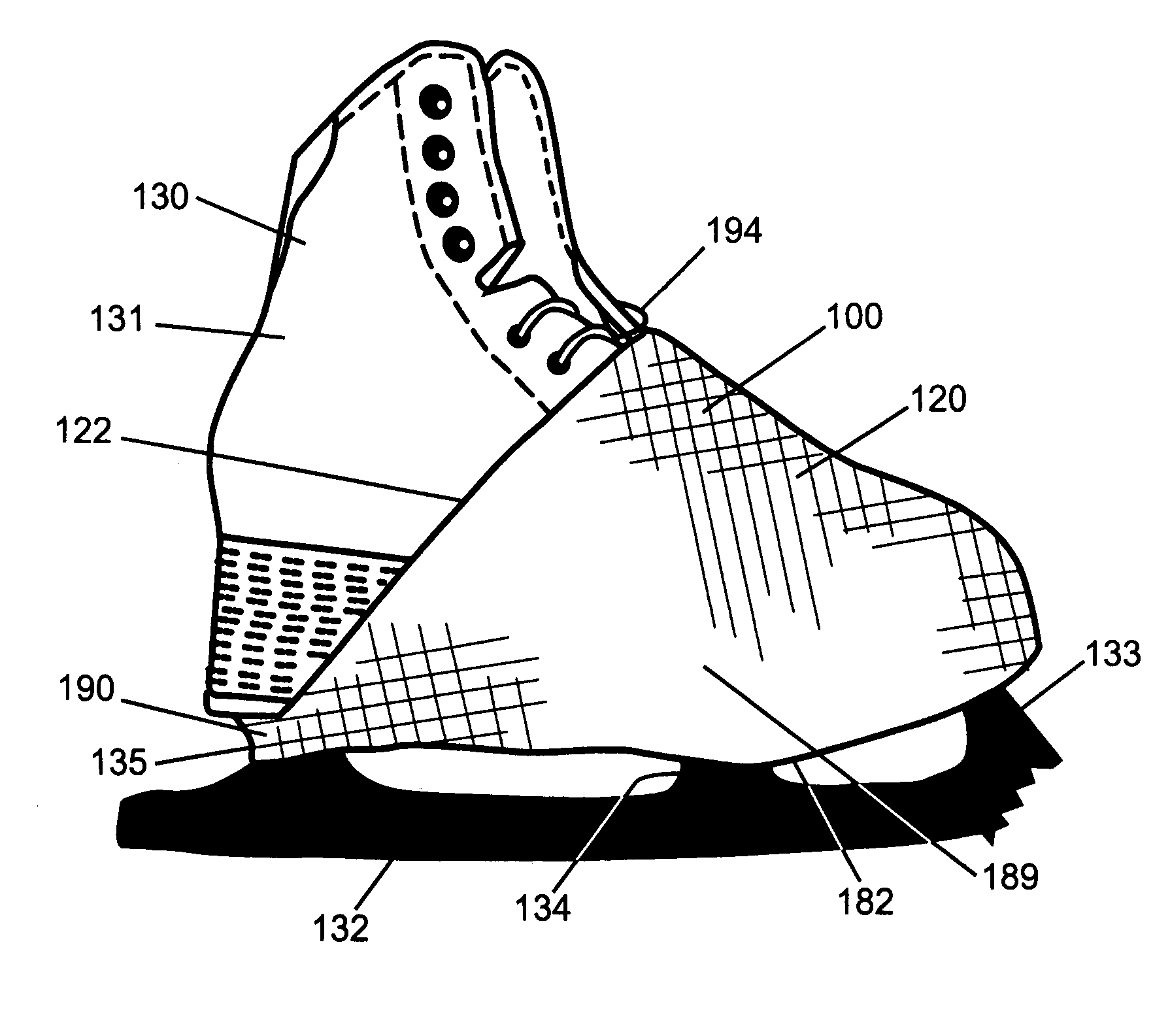
[0072]FIG. 9 is a view of the bottom of an ice skate with the blade inserted into the slit showing the method of applying the cover to the skate. Visible in FIG. 9 is the skate shoe 131, the blade 132, the exterior surface of the cover 120 showing the left wing 180, right wing 184, tongue 112, the distal 115 end of the slit. Also visible is the lacing hook 194. FIG. 9 shows the skate with the blade inserted into the slit and the cover body extending from the front of the skate shoe.

[0073]FIG. 10 is a side view of an ice skate with blade inserted into the slit further showing the method of applying the cover to the skate. Visible in FIG. 10 is the skate shoe 131, blade 132, rear stanchion 135. The exterior surface of the cover body 120 is shown, along with the right wing...


PUM


Abstract

An exemplary embodiment provides one or more improvements including inexpensive covers for providing warmth and distinctive colorations and indicia to ice skating team members. Other embodiments are adopted for use with in-line roller skates. Embodiments are constructed from a single piece of fabric. Embodiments protect the sole of the user's skate boot from contact with ice and snow.

Description

CROSS-REFERENCES TO RELATED APPLICATIONS[0001]Not Applicable.STATEMENT REGARDING FEDERALLY SPONSORED RESEARCH OR DEVELOPMENT[0002]Not Applicable.THE NAMES OF THE PARTIES TO A JOINT RESEARCH AGREEMENT[0003]Not Applicable.REFERENCE TO A “SEQUENCE LISTING,” A TABLE, OR A COMPUTER PROGRAM LISTING APPENDIX[0004]Not Applicable.BACKGROUND[0005]Embodiments relate to skate appliances or attachments.BACKGROUNDDESCRIPTION OF RELATED ART INCLUDING INFORMATION DISCLOSED UNDER 37 CFR 1.97 AND 37 CFR 1.98 [0006]Embodiments include covers for ice skates or in-line roller skates which keep warm the skater's feet, allow distinctive skate coloration, and protect the feet of skaters from injury.[0007]U.S. Pat. No. 1,160,159 discloses a skating overshoe.[0008]U.S. Pat. No. 1,714,760 discloses a shoe jacket.[0009]U.S. Pat. No. 2,029,787 discloses a foot protecting device for skaters.[0010]U.S. Pat. No. 2,109,566 discloses a skater's overshoe.[0011]U.S. Pat. No. 2,587,205 discloses a skating shoe muff.[00...

Claims


Application Information

Patent Timeline
Patent Type & Authority Applications(United States)
IPC IPC(8): A43B23/00A43B13/22
CPCA43B3/16A43B5/18A43B5/1666
Inventor IGNACIO, JENNIFER YIIGNACIO, NELSON QUIMPO
Owner IGNACIO JENNIFER YI
Learn More