Four-channel display power reduction with desaturation

a technology of desaturation and display power reduction, applied in the field of image processing techniques, can solve the problems of reducing the power of emissive displays under other conditions, increasing manufacturing costs, and increasing manufacturing costs, and reducing the power of displays

Inactive Publication Date: 2010-09-09
GLOBAL OLED TECH
View PDF20 Cites 63 Cited by
  • Summary
  • Abstract
  • Description
  • Claims
  • Application Information

AI Technical Summary

Benefits of technology

[0030]A detailed embodiment of the method of the present invention will be provided to further explain the invention and to illustrate its merits. In the method of the current invention, a four-channel emissive display is provided 12. This display can be any display having an array of subpixels that include four different colors of subpixels, which emit light in response to a modulated signal, typically a voltage or current signal. For example, this display can be an electroluminescent display, such as an organic light emitting diode (OLED) display, which has red, green, blue and white subpixels, which produce light in proportion to the current that is passed through each subpixel. These subpixels can be formed from a single plane of organic material, which emits white light, and an array of red, green, blue, and clear color filters that permit the subpixels to produce red, green, blue and white light. A cross section of such a display is depicted in FIG. 3. As shown in this figure, the OLED display is formed on a substrate 50. On this substrate 50 is formed an active matrix layer 52, which contains active matrix circuitry for providing a current to each subpixel. A patterned array of color filters 54, 56, 58, and optionally 60 are formed. The color filters 54, 56, 58, and 60 can be formed between the substrate 50 and a light-emitting layer 68. These color filters include red 54, green, 56, and blue 58 color filter materials. It can also include a clear, neutral-colored, or slightly colored filter 60 over the white subpixel to provide planarization. The color filter 60 can be an organic planarization material rather than a pigmented or dyed filter material, or can be omitted. A first array of electrodes 62 is formed over the color filters and connected to the active matrix layer 52, through vias. Pixel definition elements 64 are formed between and partially overlapping the electrodes 62. Above these electrodes 62 a continuous plane of organic materials is formed, typically including a hole transport layer 66, a light-emitting layer 68, and an electron transport layer 70. Other layers, including hole and injection layers can also be provided as is well known in the art. A second electrode layer 72 is then formed and finally an encapsulation layer 74 is formed over the second electrode layer 72. In this device structure, an electric field is provided between a segment of electrode 62 and the second electrode 72, and current flows through the OLED materials between these electrodes producing light. This light is directed substantially parallel to vector 76 and the desired spectral components of this light pass through the color filters 54, 56, 58, and optionally 60 to produce the desired color of light. In the red, green and blue subpixels 24R, 24G, 24B, undesired spectral components of the produced light are absorbed by the color filters 54, 56, 58, reducing the radiant and therefore the luminous efficiency of the light that is emitted through the narrowband red 54, green 56 and blue 58 color filters.

Problems solved by technology

However, patterning these materials for some technologies, particularly small-molecule organic EL materials, is difficult for large substrates, thereby increasing manufacturing costs.
Similarly, it is known to reduce the power of emissive displays under other conditions.
This method is disclosed with the purpose of reducing image stick artifacts, but decreases the power of the display under conditions when the display is not updated after a period of time.
In the methods for reducing the power of emissive displays through a method of driving, reducing the color saturation or luminance of the display reduces the image quality of the resulting images.
Significantly reducing the luminance of the display reduces the display contrast reducing the ability of the user to see detailed information, such as text on the display.
Reducing saturation of all color channels can reduce the image quality by producing washed out images.

Method used


Image

  • Four-channel display power reduction with desaturation
  • Four-channel display power reduction with desaturation
  • Four-channel display power reduction with desaturation

Examples


Embodiment Construction

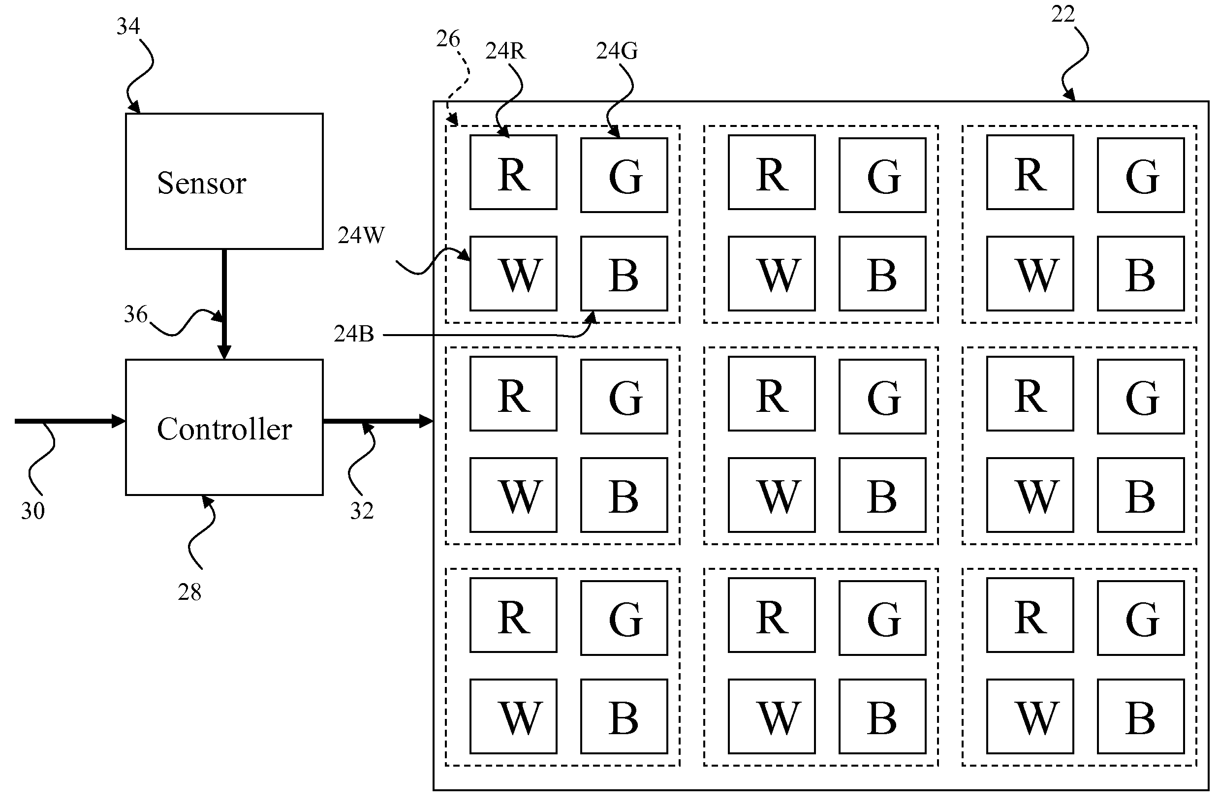
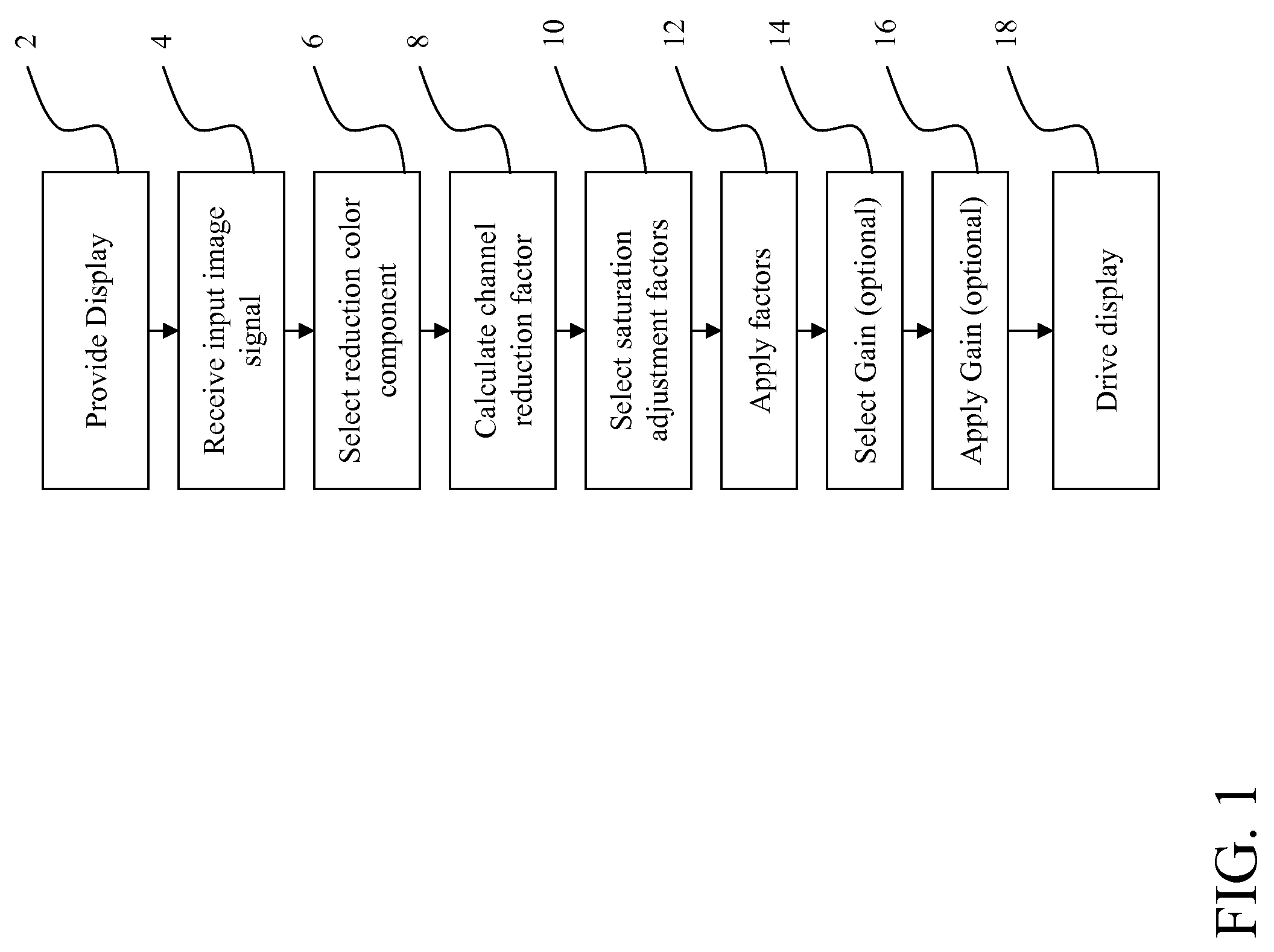
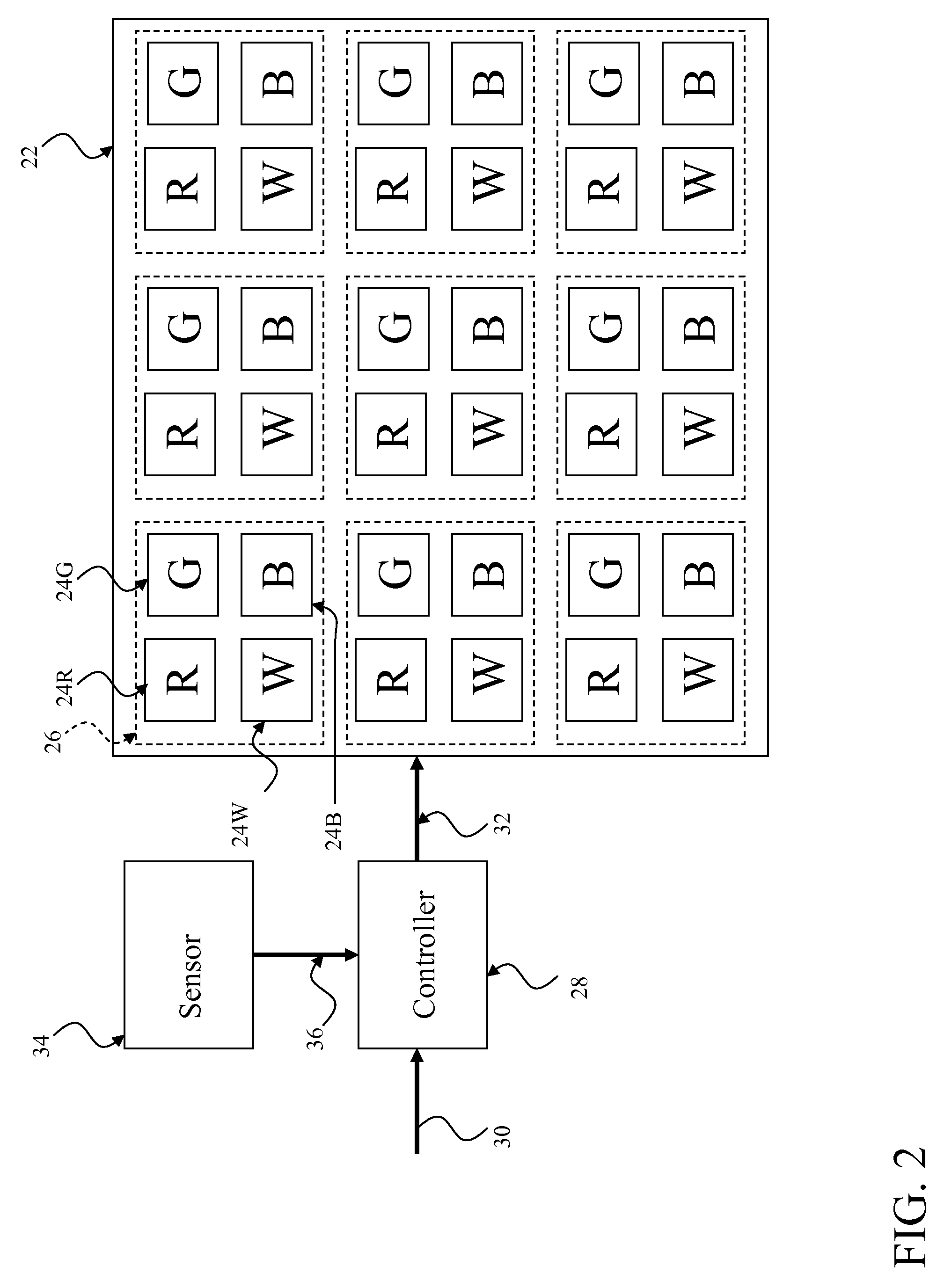
[0027]A method is provided for presenting an image on a display having color channel dependent light emission to reduce the power consumption of the display. This method includes the steps shown in FIG. 1. As shown an image input signal is received 2. This image input signal includes a plurality of input pixel signals, each input pixel signal having three color components. A reduction color component is selected 4 for reduction. A reduction factor is calculated 6 for each input pixel signal dependent upon a distance metric between the input pixel signal and the selected reduction color component. A respective saturation adjustment factor is selected 8 for each color component of each pixel signal. An image output signal is produced 10 having four color components from the image input signal using the reduction factors and saturation adjustment factors to adjust the luminance and color saturation, respectively, of the image input signal. A four-channel emissive display device is prov...


PUM


Abstract

A method of presenting an image on a display device having color channel dependent light emission comprising receiving an image input signal including a plurality of three-component input pixel signals; selecting a reduction color component; calculating a reduction factor for each input pixel signal dependent upon a distance metric between the input pixel signal and the selected reduction color component; selecting a respective saturation adjustment factor for each color component of each pixel signal; producing an image output signal having four color components from the image input signal using the reduction factors and saturation adjustment factors to adjust the luminance and color saturation, respectively, of the image input signal; providing a four-channel display device having color channel dependent light emission; and applying the image output signal to the display device to cause it to present an image corresponding to the image output signal.

Description

CROSS REFERENCE TO RELATED APPLICATIONS[0001]Reference is made to commonly-assigned, co-pending U.S. patent application Ser. No. 12 / 172,440, filed Jul. 14, 2008, entitled “Method For Improving Display Lifetime” by Miller, and commonly-assigned, co-pending U.S. patent application Ser. No. 12 / 174,085, filed Jul. 16, 2008, entitled “Converting Three-Component To Four-Component Image” by Miller et al., the disclosures of which are incorporated herein.FIELD OF THE INVENTION[0002]The present invention relates to image processing techniques for presenting images on displays having color channel dependent light emission, and more particularly, to methods for providing images with reduced power consumption or increased luminance on emissive displays having four colors of subpixels.BACKGROUND OF THE INVENTION[0003]Flat-panel display devices are widely used in conjunction with computing devices, in portable devices, and for entertainment devices. Such displays typically employ a plurality of p...

Claims


Application Information

Patent Timeline
Patent Type & Authority Applications(United States)
IPC IPC(8): G09G5/10G09G3/36
CPCG09G3/2003G09G3/3208G09G2300/0452G09G2360/144G09G2320/0626G09G2320/0666G09G2330/021G09G2320/041G09G5/02G09G3/20G09G5/10G09G3/3413G09G3/3607G09G5/04G09G2320/0233G09G2320/0271G09G2320/0613
Inventor MILLER, MICHAEL E.WHITE, CHRISTOPHER J.
Owner GLOBAL OLED TECH
Why Eureka
Try Eureka