
Method for Inkjet Printing of E13B Magnetic Ink Character Recognition Characters and Substrate Having Such Characters Printed Thereon

a magnetic ink character recognition and inkjet printing technology, applied in the field of printing, can solve the problems of reducing the peak amplitude, character unrecognizable to the automated detection system, and affecting the magnetic acuity of the detection edge,

Active Publication Date: 2010-09-23
DELPHAX TECH
View PDF22 Cites 10 Cited by
  • Summary
  • Abstract
  • Description
  • Claims
  • Application Information

AI Technical Summary

Benefits of technology

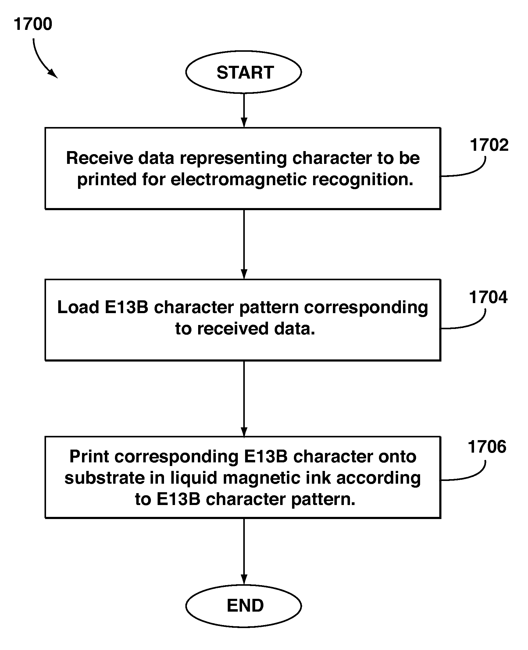
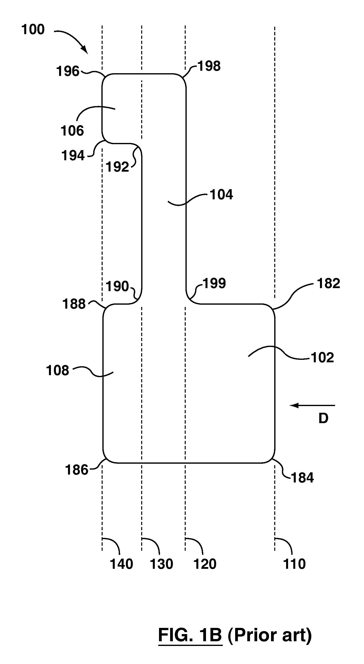
[0023]In one embodiment of the method, the character is a “1”, and the step of loading the E13B character pattern corresponding to the received data comprises loading an E13B character pattern for the “1” which includes at least one substantially linear void arrangement that is substantially parallel to, immediately adjacent, and downstream of, relative to a read direction, a last internal detection edge defined by a transition from some fill to less fill, measured perpendicular to the read direction. In a particular embodiment, the step of loading the E13B character pattern corresponding to the received data further comprises loading an E13B character pattern for the “1” which comprises a leading base portion, a stem portion, a serif portion and a trailing base portion, in which the last internal detection edge defined by a transition from some fill to less fill is defined by a transition between the stem portion and the serif and trailing base portions, and which includes a first substantially linear void arrangement within the trailing base portion and a second substantially linear void arrangement within the serif portion.
[0024]In another embodiment of the method, the character is a “3”, and the step of loading the E13B character pattern corresponding to the received data comprises loading an E13B character pattern for the “3” which includes a substantially linear void arrangement that is substantially parallel to, immediately adjacent, and upstream of, relative to a read direction, a first internal detection edge defined by a transition from some fill to more fill, measured perpendicular to the read direction. In a particular embodiment, the step of loading the E13B character pattern corresponding to the received data further comprises loading an E13B character pattern for the “3” comprising a lower leading portion, a stem portion, and three horizontally extending members, in which the first internal detection edge defined by a transition from some fill to more fill is defined between the lower leading portion and the stem portion, and which includes a substantially linear void arrangement within the lower leading portion.
[0025]In a further embodiment of the method, the character is an “8”, and the step of loading the E13B character pattern corresponding to the received data comprises loading an E13B character pattern for the “8” which includes a first substantially linear void arrangement that is substantially parallel to, immediately adjacent

Problems solved by technology

A rough detection edge reduces the acuity and therefore reduces the amplitude of the peak, which can make the character unrecognizable to the automated detection system.
However, for E13B MICR characters printed using inkjet printing, the magnetic acuity of the detection edges can be affected by the absorbency of the paper that the character is printed on.
The above-noted problems with inkjet printing of E13B MICR characters can reduce the amplitude of the peak associated with a detection edge, which can thereby make it more difficult to recognize E13B MICR characters printed using an inkjet process.
Where the automated character recognition systems cannot identify a character, then the document must be redirected for costly manual processing.
However, such special types of papers are usually more expensive, and may have a different “look and feel”, than the papers on which E13B MICR characters are normally or preferably printed.
Moreover, such special papers may be unsuitable for automatic processing.
Thus, in many cases the use of a specialized paper to enable inkjet printing of readable E13B MICR characters may be expensive, infeasible and / or undesirable.

Method used


Image

  • Method for Inkjet Printing of E13B Magnetic Ink Character Recognition Characters and Substrate Having Such Characters Printed Thereon
  • Method for Inkjet Printing of E13B Magnetic Ink Character Recognition Characters and Substrate Having Such Characters Printed Thereon
  • Method for Inkjet Printing of E13B Magnetic Ink Character Recognition Characters and Substrate Having Such Characters Printed Thereon

Examples


Embodiment Construction

[0052]As indicated above, the automatic reading apparatus used to read E13B MICR characters relies on the position and amplitude of the peaks of the waveform generated by passing the read head over the E13B MICR characters to identify those characters. More particularly, each E13B MICR character should produce a waveform having a known pattern, and industry standards have been established for the position and amplitude of the peaks for each E13B character. As such, if the position or amplitude of a peak is not within the limits stated by the E13B standard, the character cannot be reliably identified.

[0053]As noted above, a particular peak is caused by a detection edge. A detection edge is a vertical (i.e. perpendicular to the read direction) edge representing a transition, in the read direction, from (a) no magnetic ink to some magnetic ink; (b) some magnetic ink to no magnetic ink; (c) some magnetic ink to more magnetic ink; or (d) some magnetic ink to less magnetic ink. It has bee...


PUM


Abstract

Electromagnetically recognizable E13B characters can be printed onto conventional paper by an inkjet printer using liquid magnetic ink. The printer receives data representing an E13B character, and prints the E13B character onto a substrate according to a modified E13B character pattern. The modified E13B pattern provides for an interior of the E13B character to be substantially completely filled, and includes one or more void arrangements arranged and positioned relative to a corresponding internal detection edge, and sized and shaped, to amplify the difference between the upstream magnetic signal detected on the upstream side of the internal detection edge and the downstream magnetic signal detected on the downstream side of the internal detection edge when an electromagnetic read head reads the resulting printed E13B character.

Description

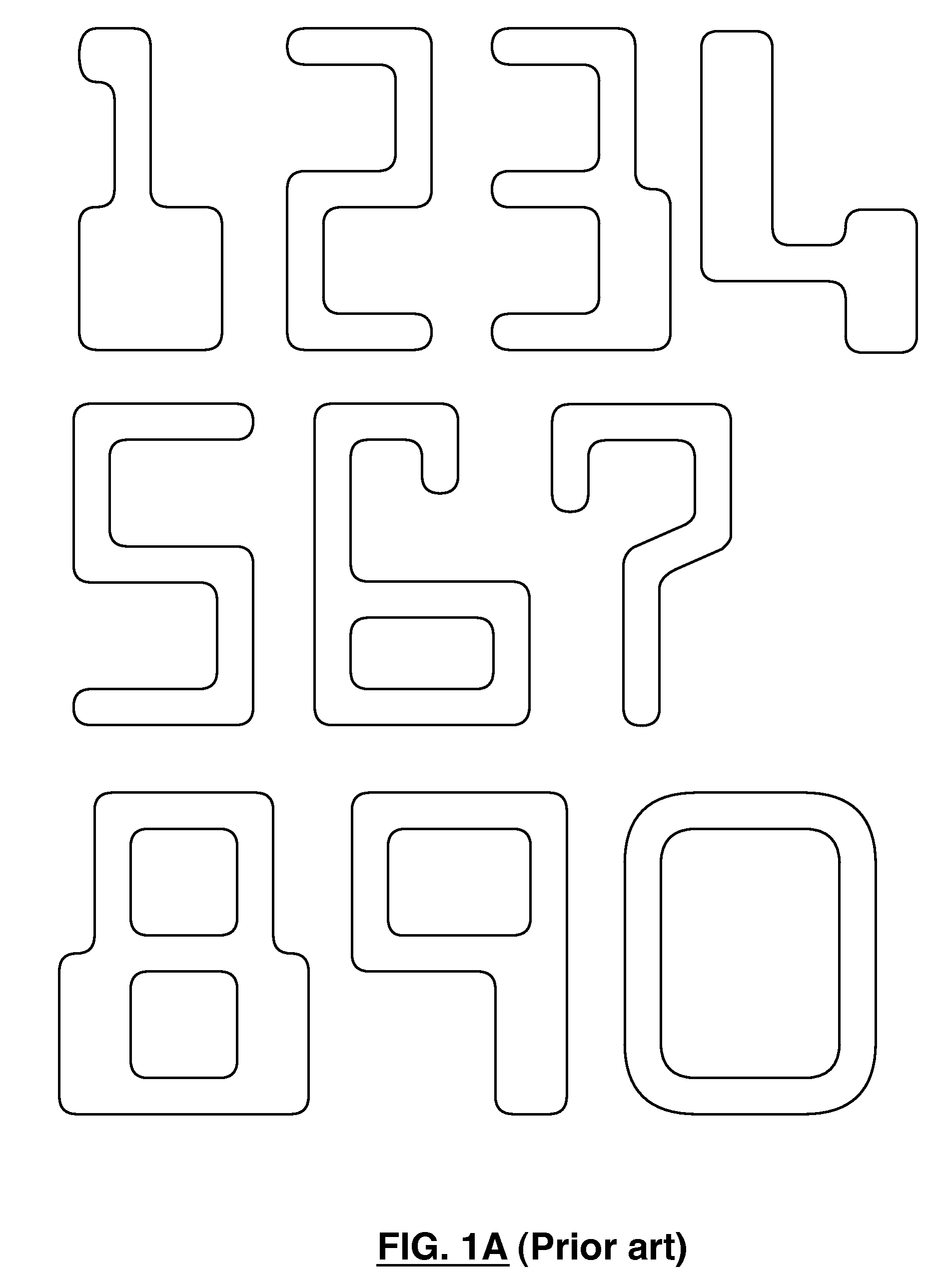
FIELD OF INVENTION[0001]The present invention relates to printing, and more particularly to printing of E13B magnetic ink character recognition (MICR) characters.BACKGROUND OF THE INVENTION[0002]In the financial industry, checks are commonly printed with MICR characters to facilitate automated processing of those checks. MICR characters are printed using magnetic ink or toner, that is, ink or toner that contains magnetic particles dispersed throughout, so that the characters can be read automatically by a data processing system that includes a suitable electromagnetic read head. One widely used standard for such characters is the E13B standard, which defines with specificity the patterns and relative dimensions of the numerical characters 1, 2, 3, 4, 5, 6, 7, 8, 9 and 0, as well as a number of special characters. The E13B patterns for the numerical characters 1, 2, 3, 4, 5, 6, 7, 8, 9 and 0 are shown in FIG. 1. The ANSI (American National Standards Institute) standard for the E13B c...

Claims


Application Information

Patent Timeline
IPC IPC(8): B41J29/38G06V30/224
CPCB41J2/175B41J3/01B41J29/393G06K2215/0082G06K9/186G06K15/00G06K19/06187G06K9/036G06V30/2253G06V10/993
Inventor THOMSON, CHRISTOPHER WILLIAMMCCALLUM, ROBERT STUARTFOYLE, VICTOR PETER
Owner DELPHAX TECH
Learn More