One chip image sensor for measuring vitality of subject

a vitality measurement and image sensor technology, applied in the field of image sensors, can solve the problems of increased cost, complicated operation, difficult manipulation, etc., and achieve the effect of measuring the vitality of the subj

Active Publication Date: 2010-09-30
OPTOLANE TECH
View PDF6 Cites 70 Cited by
  • Summary
  • Abstract
  • Description
  • Claims
  • Application Information

AI Technical Summary

Benefits of technology

The technical effect of this patent is that it describes methods for measuring the vitality or energy level of a person's body using images captured by an image sensor. These methods involve analyzing different colors and infrared levels in the reflective light received from the person's body. By comparing these data points, researchers hope to better understand how well someone is doing physically and emotionally.

Problems solved by technology

This patent describes a way to measure the health and quality of vegetation based on its reflection of near-infrared light. However, current methods require expensive equipment and complex procedures to obtain both visual and infrared images. Therefore, there is a technical problem that needs to be solved to make this process more efficient and economically viable.

Method used


Image

  • One chip image sensor for measuring vitality of subject
  • One chip image sensor for measuring vitality of subject
  • One chip image sensor for measuring vitality of subject

Examples


Embodiment Construction

[0021]The attached drawings for illustrating exemplary embodiments of the present invention are referred to in order to gain a sufficient understanding of the present invention, the merits thereof, and the objectives accomplished by the implementation of the present invention.

[0022]Hereinafter, the present invention will be described in detail by explaining exemplary embodiments of the invention with reference to the attached drawings. Like reference numerals in the drawings denote like elements.

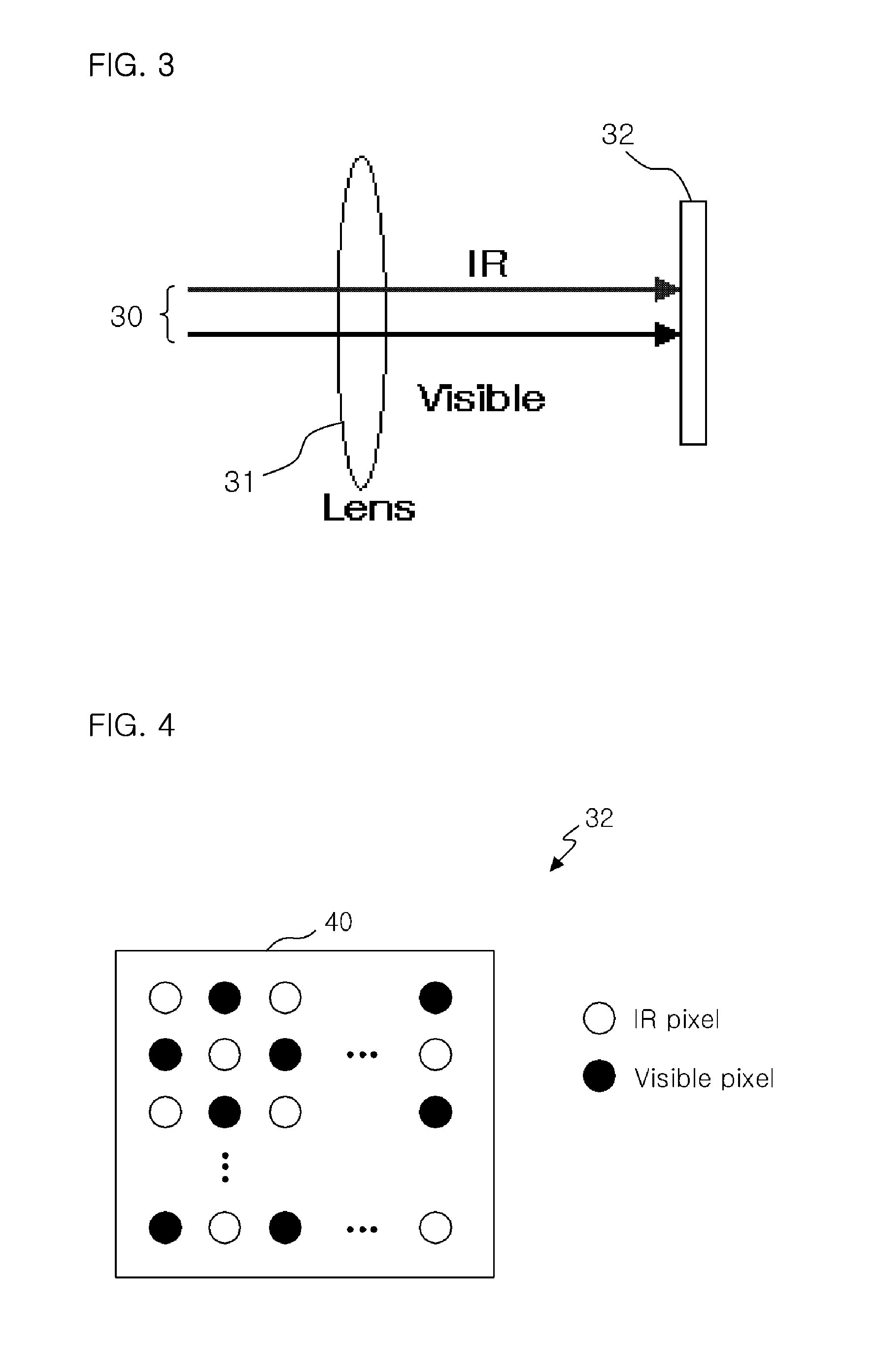
[0023]FIG. 3 is a view for explaining a method of using an image sensor according to an embodiment of the present invention.

[0024]Referring to FIG. 3, light 30 including visible light and IR light is incident on a lens 31 to be transmitted to an image sensor 32.

[0025]The image sensor 32 has a pixel array shown in FIG. 4.

[0026]Referring to FIG. 4, visible pixels and IR pixels are alternately disposed on a chip 40.

[0027]FIG. 5 is a view showing characteristics of filters passing blue (B), gree...


PUM


Abstract

Provided is a one-chip vitality measuring image sensor. The image sensor includes one chip where a plurality of IR pixels and a plurality of visible pixels are alternately disposed, IR pass filters which are disposed on the IR pixels, and color pass filters which are disposed on the visible pixels. In the image sensor, IR strength and color strengths are obtained from light which is incident to the IR pixels and the visible pixels, and a vitality of a subject is measured by comparing the IR strength with the color strengths.

Description


Claims


Application Information

Patent Timeline
Owner OPTOLANE TECH
Why Eureka
Try Eureka