Control apparatus and method for automatic transmission

Active Publication Date: 2010-09-30
JATCO LTD +1
View PDF0 Cites 40 Cited by
  • Summary
  • Abstract
  • Description
  • Claims
  • Application Information

AI Technical Summary

Benefits of technology

[0007]It is therefore an object of the present invention to provide control apparatus and method for an automatic transmission, devised to suppress the occurrence of shift shock which is

Problems solved by technology

Hence, in a case that the state of transmission is transferred from the torque phase directly to the inertia phase without passing through the neutral state, the fuel cut recovery control cannot be activated at a proper timing so that the fuel cut recovery is carried out before a start of torque phase or during the inertia phase.
In such cases, a recovery shock is caused.
However, the time length between a time point when a piston stroke has just been done up to its

Method used


Image

  • Control apparatus and method for automatic transmission
  • Control apparatus and method for automatic transmission
  • Control apparatus and method for automatic transmission

Examples


Example

First Embodiment

[0027]A first embodiment of automatic-transmission control apparatus and method according to the present invention will be explained below referring to the drawings.

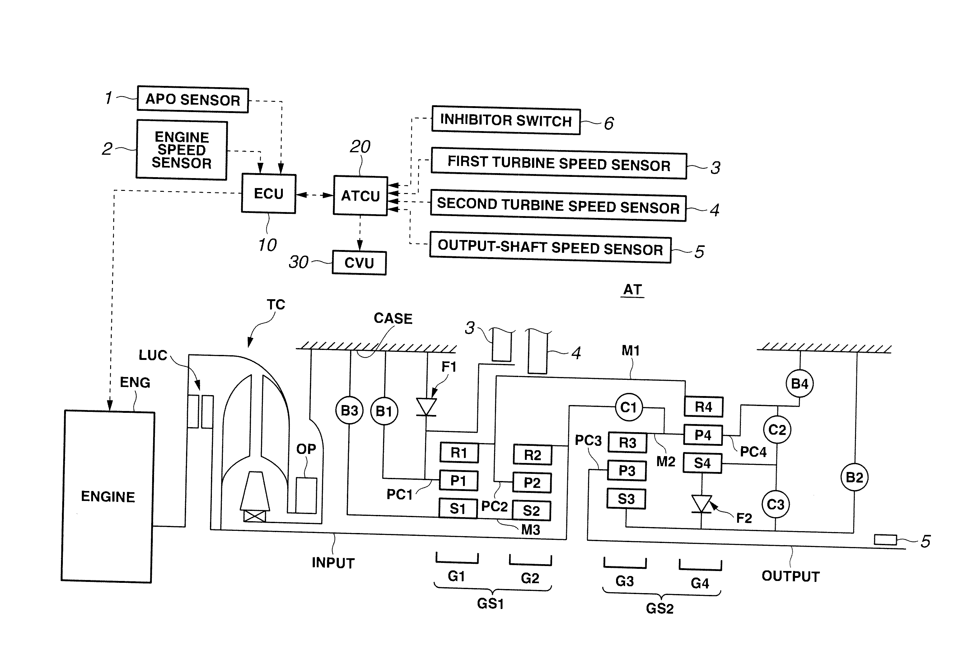
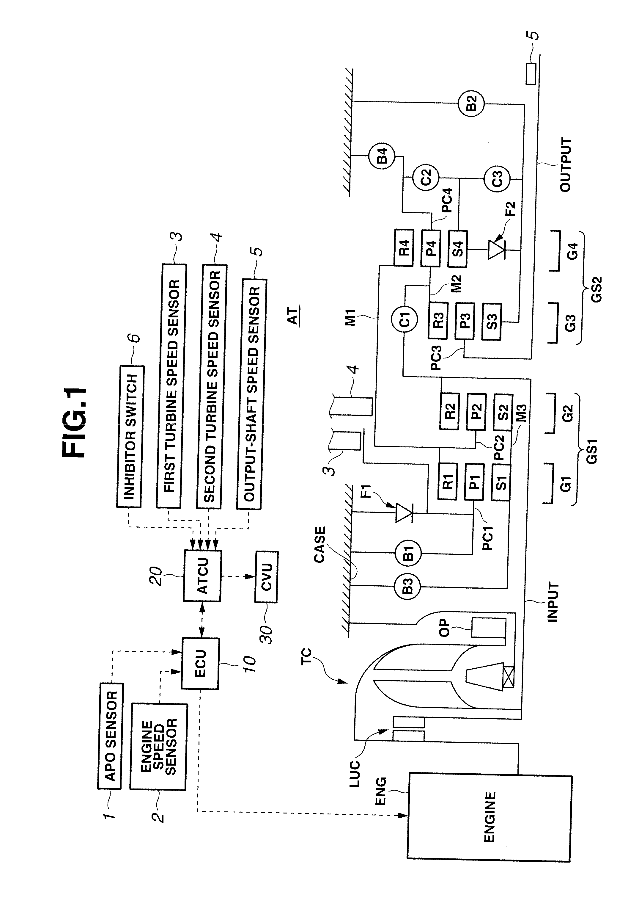
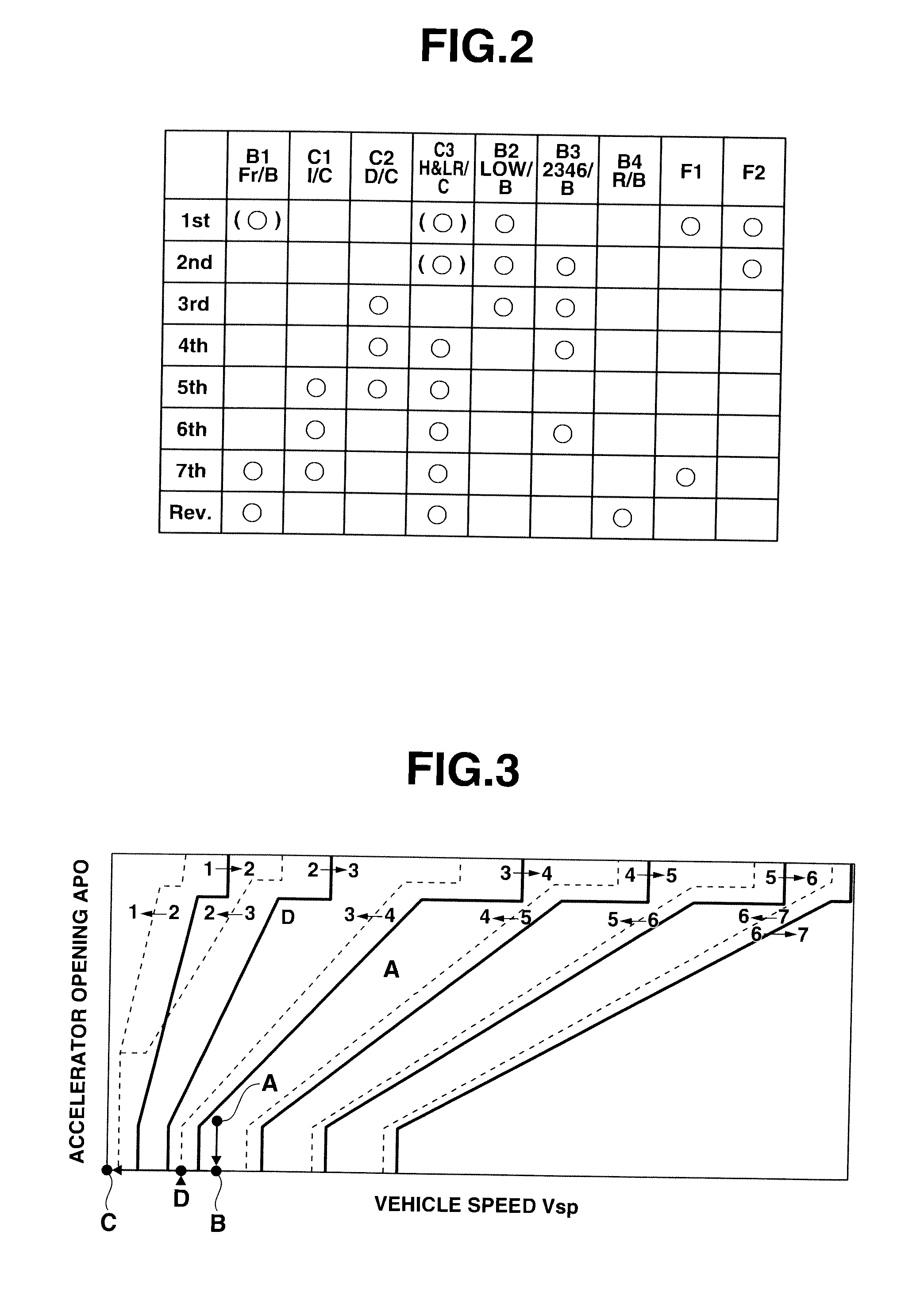
[0028]At first, a configuration in the first embodiment is now explained. FIG. 1 is a skeleton diagram showing an automatic transmission AT (one example of automatic transmission) to which the control apparatus according to the present invention has been applied according to the first embodiment. This automatic transmission AT has forward seven speeds (seven transmission ratios, i.e., seven shift steps) and reverse one speed. FIG. 2 is an engaging-operation table showing engagement states of respective friction(-engagement) elements for each transmission ratio (each shift step) in the automatic transmission AT to which the shift control apparatus in the first embodiment is applied. FIG. 3 is a shift diagram showing one example of shift map which is used for the shift control in the first embodiment when a...


PUM


Abstract

A control apparatus includes a shift-pressure learning correction controlling section configured to perform a shift-pressure learning correction in which a physical quantity representing a progress of shift is measured at a time of current downshift, and in which an engagement command pressure for a friction element is corrected at a time of next downshift on the basis of a divergence between the measured physical quantity and a target physical quantity; a shift-torque increase controlling section configured to perform a torque increase control in which a command for temporarily increasing torque of a drive source starts to be outputted when a start estimation timing of torque phase has just come during a transition period given between start and end of the downshift; and a learning convergence judging section configured to judges whether the shift-pressure learning correction has converged, configured to prohibit the torque increase control until it is decided that the shift-pressure learning correction has converged, and configured to permit the torque increase control when it is decided that the shift-pressure learning correction has converged.

Description

BACKGROUND OF THE INVENTION[0001]The present invention relates to control apparatus and method for an automatic transmission, capable of performing a shift-torque increase control for temporarily increasing torque of a drive source against pull-in torque, e.g., at a time of coast downshift caused by an accelerator release.[0002]U.S. Pat. No. 7,503,873 (corresponding to Japanese Patent Application publication No. 2006-69267) discloses a previously proposed control apparatus for an automatic transmission. In this technique, a fuel cut recovery is started during the coast downshift conducting a fuel cut, by detecting a drop of turbine rotational speed which occurs when a high-speed-side engagement element (friction element) is released so as to cause a neutral state.[0003]In this technique, by carrying out a fuel cut recovery control during the downshift, a pull-in amount of torque is reduced during a torque phase before a start of inertia phase so that a pull-in shock is suppressed.[0...

Claims


Application Information

Patent Timeline
IPC IPC(8): G06F19/00F16H59/40F16H59/74F16H61/08F16H61/68F16H61/684F16H61/686F16H63/40F16H63/50
CPCB60W30/18072F16H61/061F16H2061/0087F16H63/502F16H61/686F16H2059/186B60W2710/0666B60W2710/1083B60W2050/0088B60W2510/108B60W30/19B60W2050/0094B60W10/11B60W10/06Y02T10/60B60W2556/10B60W2050/0075B60W10/00B60W10/10B60W50/00F16H61/00F16H61/06F16H61/08F16H61/10F16H63/50
Inventor HIRASAKO, KAZUKISUZUKI, MASAMI
Owner JATCO LTD
Why Eureka
Try Eureka