Nail-Plate Combination

a nail-plate and joint technology, applied in the field of bone fixation implants, can solve the problems of poor bone purchase, post-operative complications, proximal humeral fractures (fractures of the head or cortex), etc., and achieve the effect of limiting the scope of invention

Active Publication Date: 2010-10-07
DEPUY SYNTHES PROD INC
View PDF6 Cites 22 Cited by
  • Summary
  • Abstract
  • Description
  • Claims
  • Application Information

AI Technical Summary

Problems solved by technology

As understood by those skilled in the art, proximal humeral fractures (fractures of the head or cortex) often result from a fall on the humerus.
Poor bone purchase is often a result of osteoporosis.
Post-operative complications may arise when the patient applies a load to the healing bone.
For example, a screw may be forced out of the humeral head or a plate may bend or break.

Method used


Image

  • Nail-Plate Combination
  • Nail-Plate Combination
  • Nail-Plate Combination

Examples


Embodiment Construction

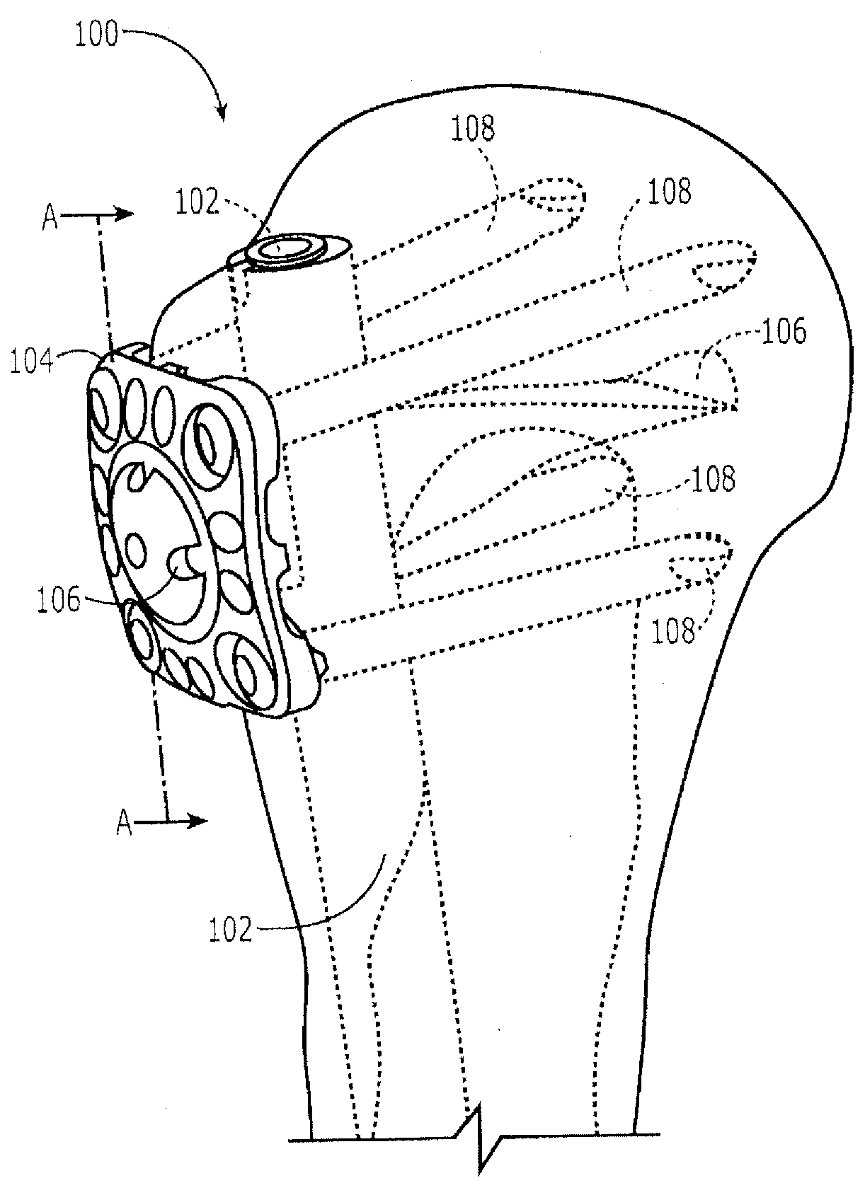
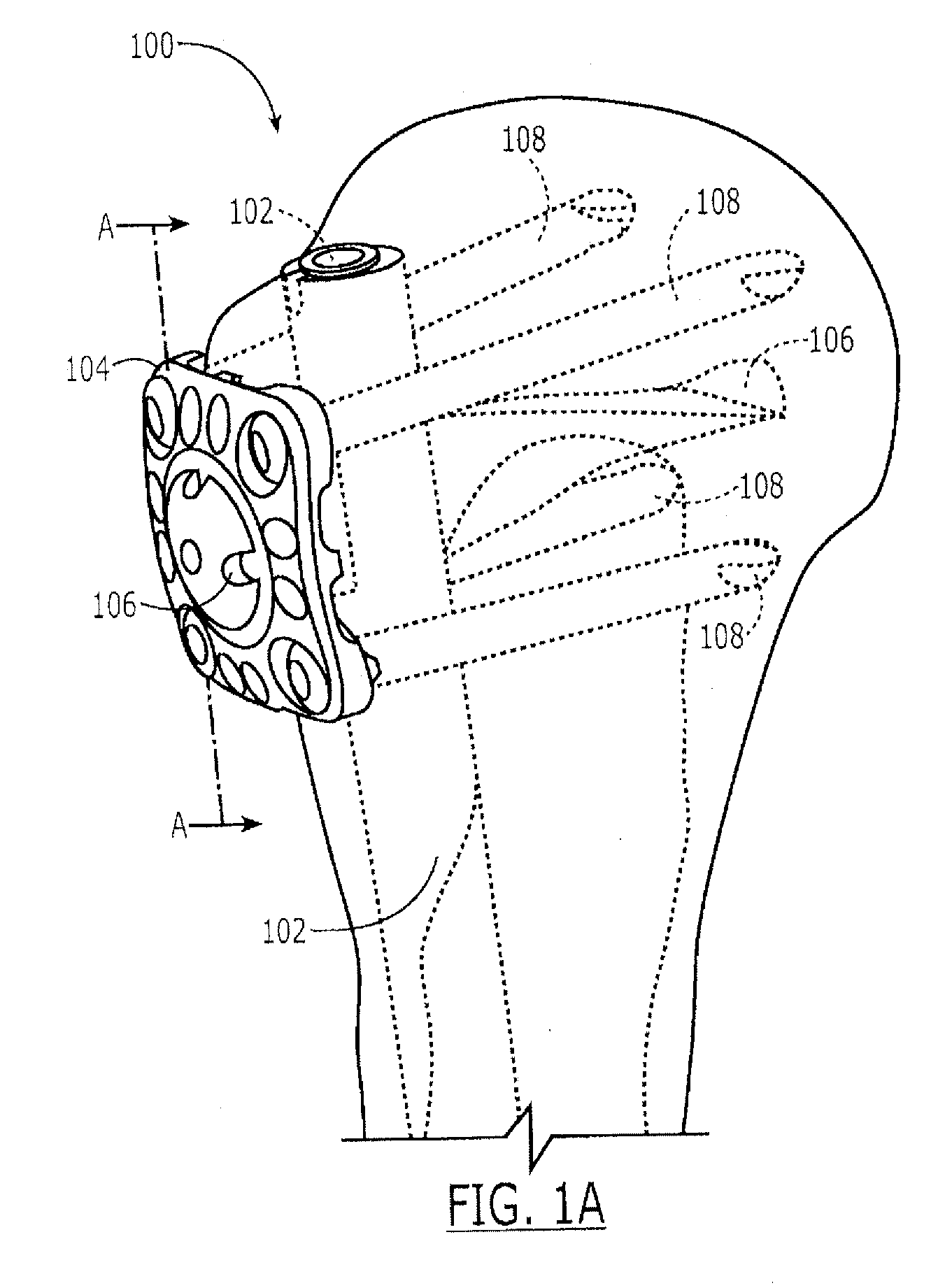
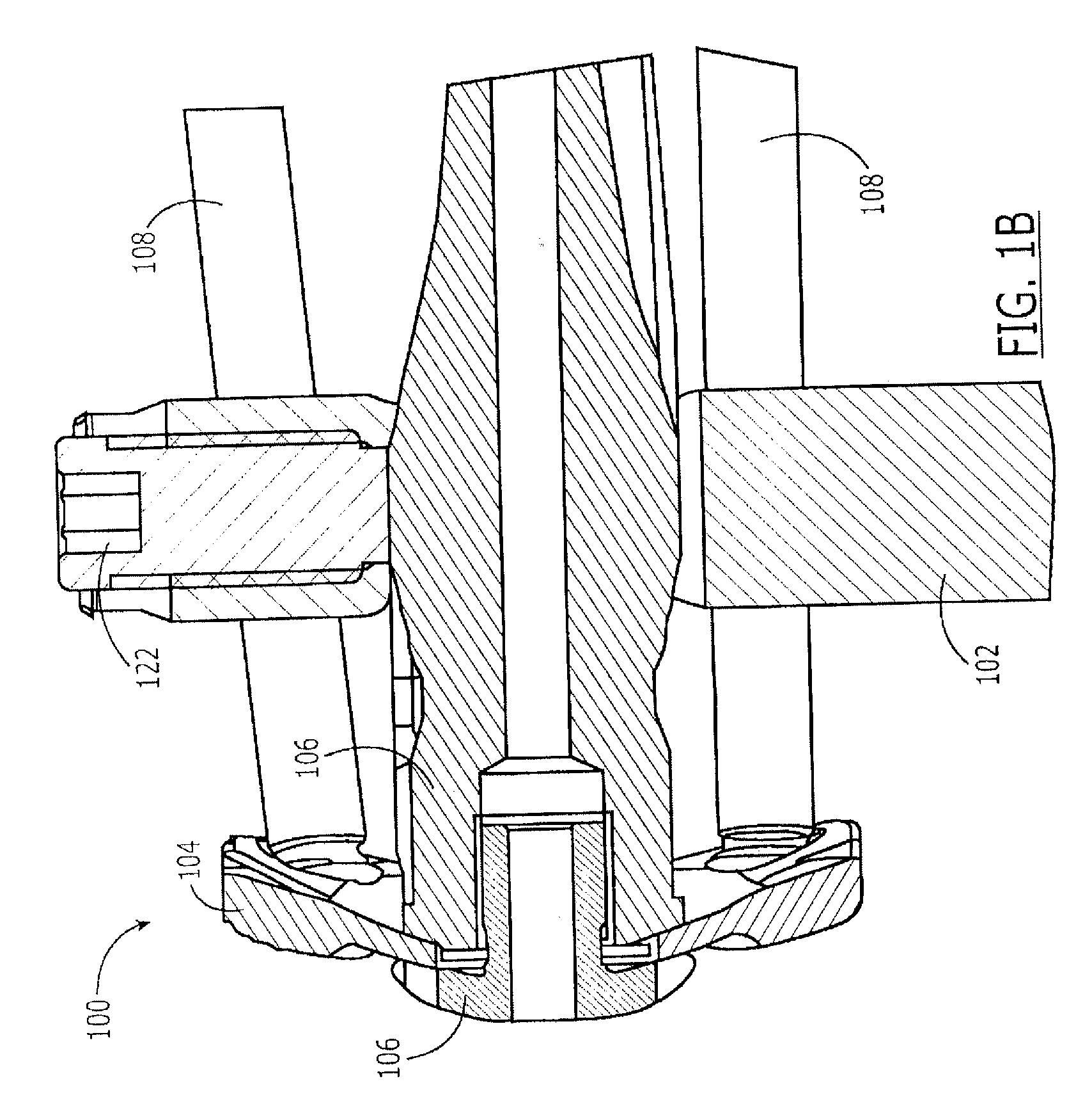
[0063]The present invention, which may be further understood with reference to the following description and the appended drawings, relates to systems and methods for providing fixation of bone fractures. Specifically, the present invention relates to nail and plate combinations that may be used to fix multipart fractures of one end of a bone. Exemplary embodiments of the present invention describe, for example, a combination comprising a plate and an intramedullary nail. It should be noted that directional references used herein do not refer to particular frames of reference (e.g., the horizontal), but are employed merely to indicate directions relative to other parts of the devices described unless they specifically address direction relative to an external feature such as a bone. For example, the term top refers to a surface of a plate which, when placed on a bone in a desired orientation, faces away from the bone while a bottom refers to a surface facing the bone.

[0064]As shown ...


PUM


Abstract

A device for treating a bone includes a plate having a connector opening and a first fastener receiving lumen extending therethrough, the first fastener receiving lumen being sized and shaped to receive therethrough a bone fastener and a nail sized and shaped for insertion in a medullary canal of a target bone, the nail including an elongate shaft and an opening extending through the shaft in combination with a connector sized and shaped so that, when the plate is positioned over a target portion of bone in a desired alignment with the nail, the connector may be passed into the target portion of bone via the connector opening and into the opening of the nail, the shape of the connector engaging the opening to form an angularly stable connection between the plate and the nail.

Description

CROSS-REFERENCE TO RELATED APPLICATIONS[0001]The subject matter disclosed in this patent application is related to subject matter disclosed and claimed in U.S. Provisional Patent Application No. 60 / 975,729 filed Sep. 27, 2007 and U.S. Provisional Patent Application No. 60 / 981,843 filed Oct. 23, 2007 both of which are incorporated herein by reference in their entireties.FIELD OF THE INVENTION[0002]The invention relates generally to implants for bone fixation and, in particular, to implants for fixation of multi-part fractures and two-part fractures with poor bone purchase (osteoporosis) of the proximal humerus to promote osteosynthesis.BACKGROUND[0003]As understood by those skilled in the art, proximal humeral fractures (fractures of the head or cortex) often result from a fall on the humerus. In a two-part fracture, the head or a single portion of the head is broken from the humeral shaft. Multi-part fractures involve the fracture of the humeral head into two or three fragments that...

Claims


Application Information

Patent Timeline
Patent Type & Authority Applications(United States)
IPC IPC(8): A61B17/88A61B17/80
CPCA61B17/725A61B17/8061A61B17/8057A61B17/8014
Inventor PLECKO, MICHAELBOESL, OLIVER
Owner DEPUY SYNTHES PROD INC
Why Eureka
Try Eureka