Control device, head-mount display device, program, and control method

a display device and control device technology, applied in the direction of selective content distribution, television systems, instruments, etc., can solve the problems of unintended operation, large circuit size, high cost, etc., and achieve the effect of recognizing more quickly and more accurately the operation

Inactive Publication Date: 2010-10-14
NIKON CORP
View PDF7 Cites 93 Cited by
  • Summary
  • Abstract
  • Description
  • Claims
  • Application Information

AI Technical Summary

Benefits of technology

[0011]Thus, the present invention can provide a technique according to which the head-mount display device can perform processing while recognizing more quickly and more accurately operation intended by a user.

Problems solved by technology

In the technique described in Patent Document 1, however, a user cannot use his head motion to instruct the device to perform desired operation, and thus he must manually operate the device.
Further, it is possible that unintended operation is performed due to a return motion or the like of the user's head.
And in the technique described in Patent Document 2, both types of sensors, i.e. gyro sensors and magnetic sensors are used to correct an attitude, and thus the circuit size becomes larger and costs higher, and in addition higher computing power is required.

Method used


Image

  • Control device, head-mount display device, program, and control method
  • Control device, head-mount display device, program, and control method
  • Control device, head-mount display device, program, and control method

Examples


first embodiment

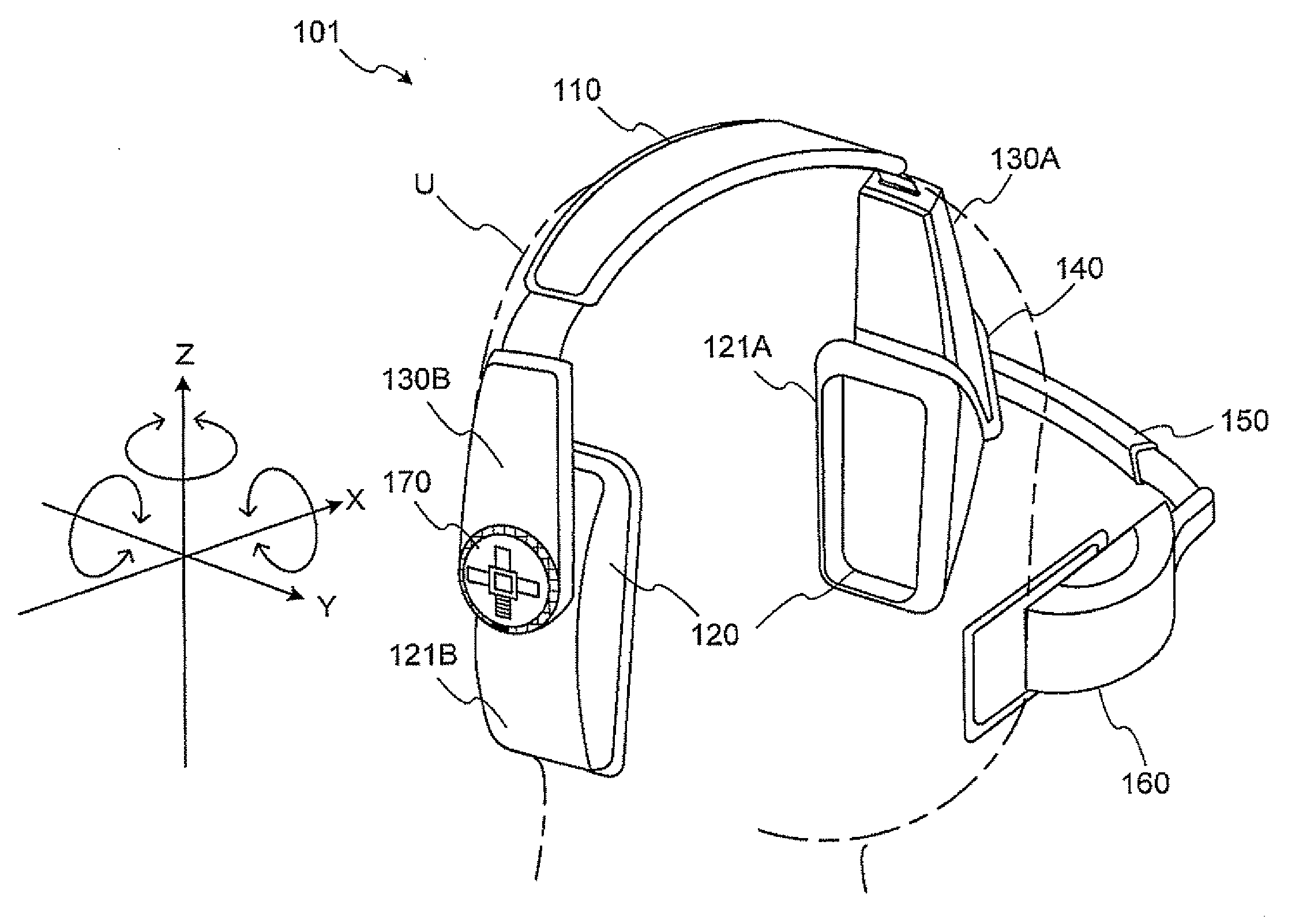
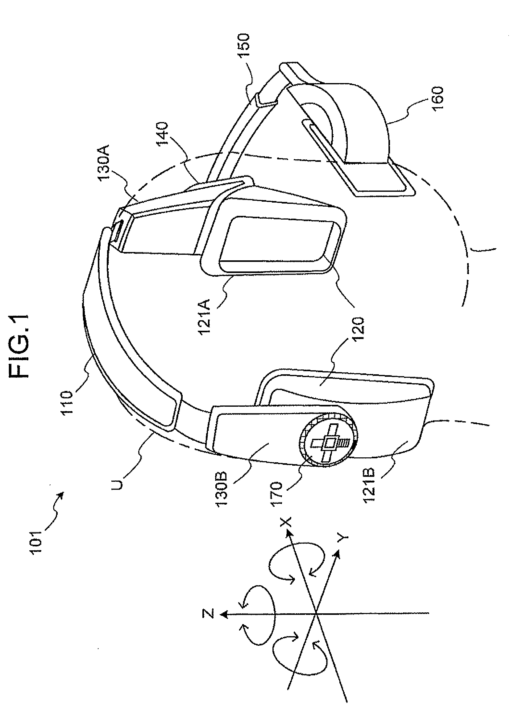
[0045]A head-mount display device (hereinafter, briefly referred to as HMD) 101 of the present embodiment identifies different kinds of processing instructed by user's motions in the same direction, on the basis of the amplitude of the head motion, while preventing execution of unintended processing caused by a return motion of the user's head.

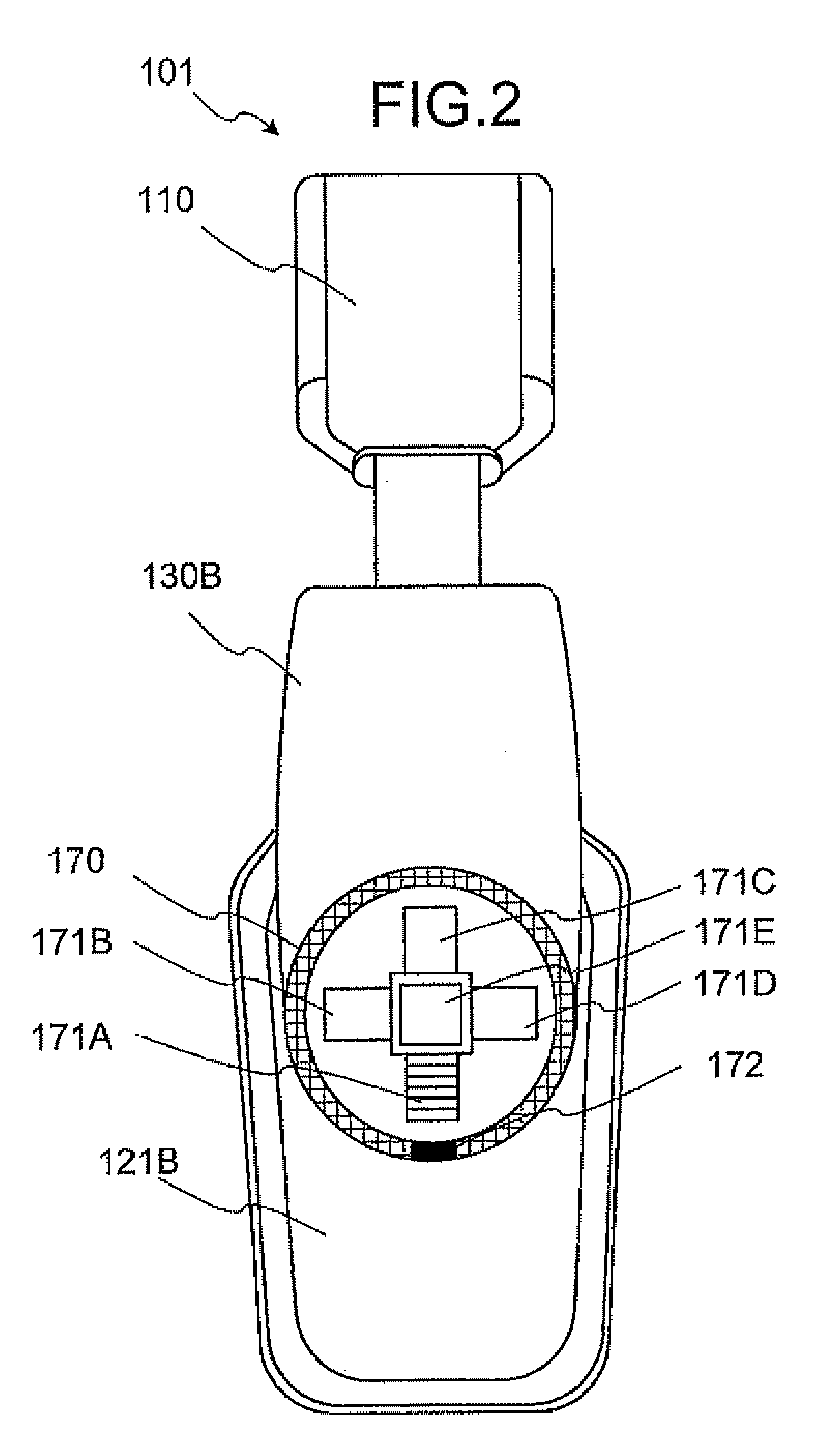
[0046]FIGS. 1 and 2 show the head mount display device 101. FIG. 1 is a perspective view showing the HMD 101 of the first embodiment of the present invention, and FIG. 2 is a side view showing the HMD 101 of the first embodiment.

[0047]As shown in the figures, the HMD 101 of the present embodiment comprises a head-mounting band 110, a sound output unit 120, housings 130A and 130B, a supporting unit 140, an arm unit 150, a display unit 160, and an operation unit 170.

[0048]The head-mounting band 110 is formed into a curved shape such that both ends face each other. Further, the head-mounting band 110 is made of elastic material, so that speakers ...

second embodiment

[0135]Next, a second embodiment of the present invention will be described. In the following, an HMD 102 as the second embodiment will be described with respect to different points from the first embodiment.

[0136]The HMD 102 of the second embodiment of the present invention differs from the first embodiment in that the HMD 102 displays an indicator expressing angular velocities visually. FIG. 11 is a block diagram showing a functional configuration of the HMD 102.

[0137]A control unit 410 will be described. The control unit 410 comprises a motion analysis unit 411, a time measuring unit 412, a signal control unit 413, and a display bar generation unit 414.

[0138]The control unit 410 displays an indicator 800 of a cross shape as shown in FIG. 13 on a screen of a display device provided in a display unit 160.

[0139]The indicator 800 is of a cross shape having angular velocity display areas 810A, 810B, 810C and 810D (simply expressed as angular velocity display area 810 when it is not nec...

third embodiment

[0165]Next, a third embodiment of the present invention will be described. An HMD 103 of the present embodiment is also similar to the HMD 101 of the first embodiment, and thus description of the same components will be omitted.

[0166]The HMD 103 of the third embodiment of the present invention differs from the HMD of the first embodiment in that corrected coordinates are calculated from the coordinate system for detection by angular velocity sensors and a user's coordinate system.

[0167]When the HMD 103 is mounted on the user's head, screen operation concerning the display screen of the display unit 160 can be performed basically when the user moves his head. However, sometimes error occurs owing to user's way of mounting the HMD 103 on his head, user's way of moving his neck out of habit, or the like, and the user cannot always perform intended operation.

[0168]Thus, in order to perform accurate operation by user's own head motion, the HMD 103 of the present embodiment performs proce...


PUM


Abstract

It is possible to provide a technique for accurately performing an operation desired by a user. A user's head operation is identified according to information detected by a head motion detection unit. A process desired by the user is executed according to an angular velocity of the head motion. Moreover, the technique uses a control unit which can accurately execute an operation by the user's head operation without reflecting the return motion of the user's head in the process. The control unit executes a process for a start and an end of each process corresponding to the detected angular velocity according to a predetermined threshold value.

Description

TECHNICAL FIELD[0001]The present invention relates to a technique of detecting a motion of a human body in order to exercise specific control.BACKGROUND ART[0002]There is known a head-mount display device that detects a user's head motion and exercises control according to specific motions. For detecting a head motion, such a head-mount display device uses various kinds of sensors such as for example a gyro sensor (angular velocity sensor), an acceleration sensor, a magnetic sensor, and the like. Various techniques have been developed in order to improve operability of a head-mount display device based on such various kinds of sensors.[0003]For example, Patent Document 1 discloses a technique of reflecting a user's head motion detected by sensors on displaying of information on a display of a head-mount display device.[0004]Further, Patent Document 2 disclose a technique of using data of rotation angles detected by gyro sensors respectively around triaxial directions perpendicular t...

Claims


Application Information

Patent Timeline
Patent Type & Authority Applications(United States)
IPC IPC(8): G09G5/00G01P3/00G06F15/00G06F3/048G06F3/0485
CPCG02B27/017G02B2027/014G02B2027/0187H04N21/42222G06F3/0485H04N2005/4428H04N21/42219G06F3/012H04N21/41265
Inventor TAKANO, SEIJIOTSUKI, MASAKISUGA, AKINOBUFUJINAWA, NOBUHIROKURIBAYASHI, HIDENORI
Owner NIKON CORP
Why Eureka
Try Eureka