
Deflaker plate and methods relating thereto

a technology of deflaker plate and plate, which is applied in the field of systems and methods for reducing flake, can solve the problems of inability to machining the plate, high manufacturing cost and limit, and the amount of time and energy used in the pulper to achieve the full fiberized state, etc., and achieve the effect of reducing fibrous flakes

Active Publication Date: 2010-10-28
ANDRITZ INC
View PDF1 Cites 6 Cited by
  • Summary
  • Abstract
  • Description
  • Claims
  • Application Information

AI Technical Summary

Benefits of technology

[0011]In an aspect, the invention generally relates to a deflaker plate for use in a deflaker for reducing fibrous flakes in a slurry of fibers. The deflaker plate may include at least one annular ring consisting of multiple teeth, in which at least one tooth has a leading face, a trailing face, and an impact-generating side-face. The impact-generating side-face may be adapted to generate an impact force during operation, such that the force corresponds to a first vector radially pushing the slurry towards a center of the deflaker and a second vector tangentially pushing the slurry towards the leading face.

Problems solved by technology

The amount of time and energy used in the pulper to achieve the fully fiberized state, however, is usually prohibitive to the amount of production required of such central papermaking equipment.
But machining the plates involves higher manufacturing costs and a limit in the ability to specially design the opposing surfaces of the teeth.
That is, precision machining inherently places limits on the design of the deflaker plates.

Method used


Image

  • Deflaker plate and methods relating thereto
  • Deflaker plate and methods relating thereto
  • Deflaker plate and methods relating thereto

Examples


Embodiment Construction

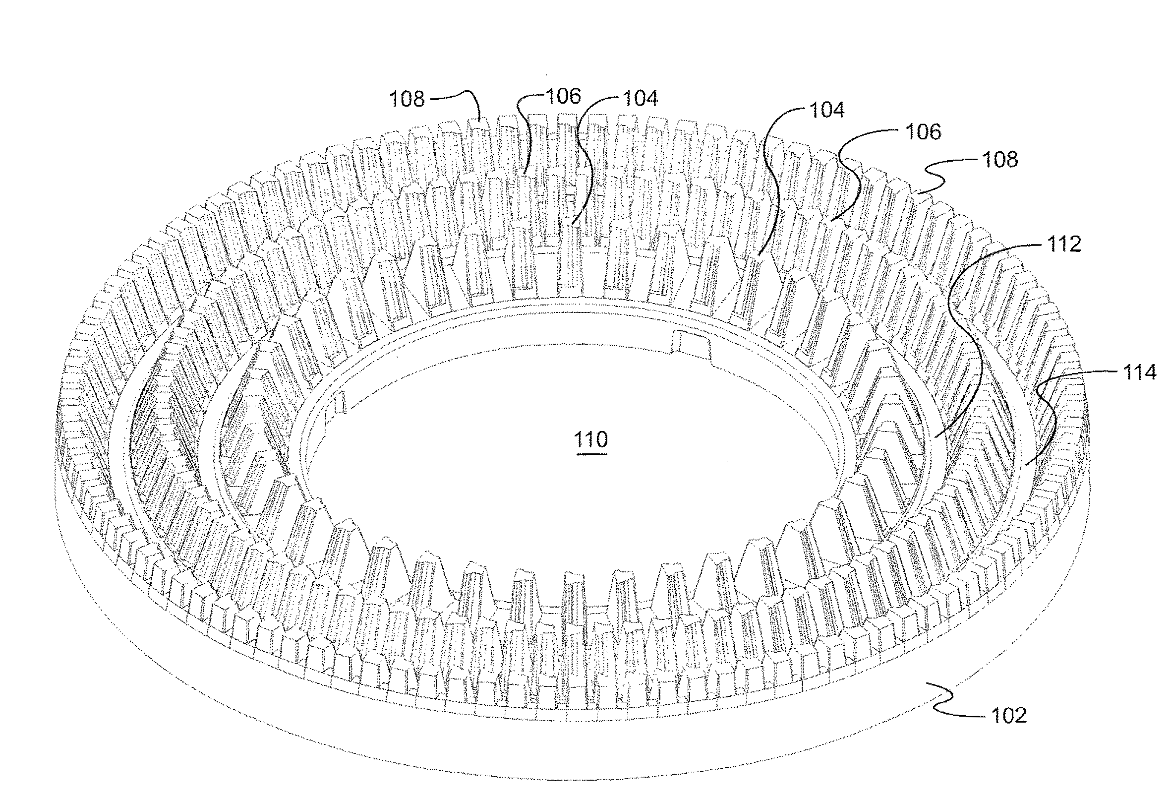
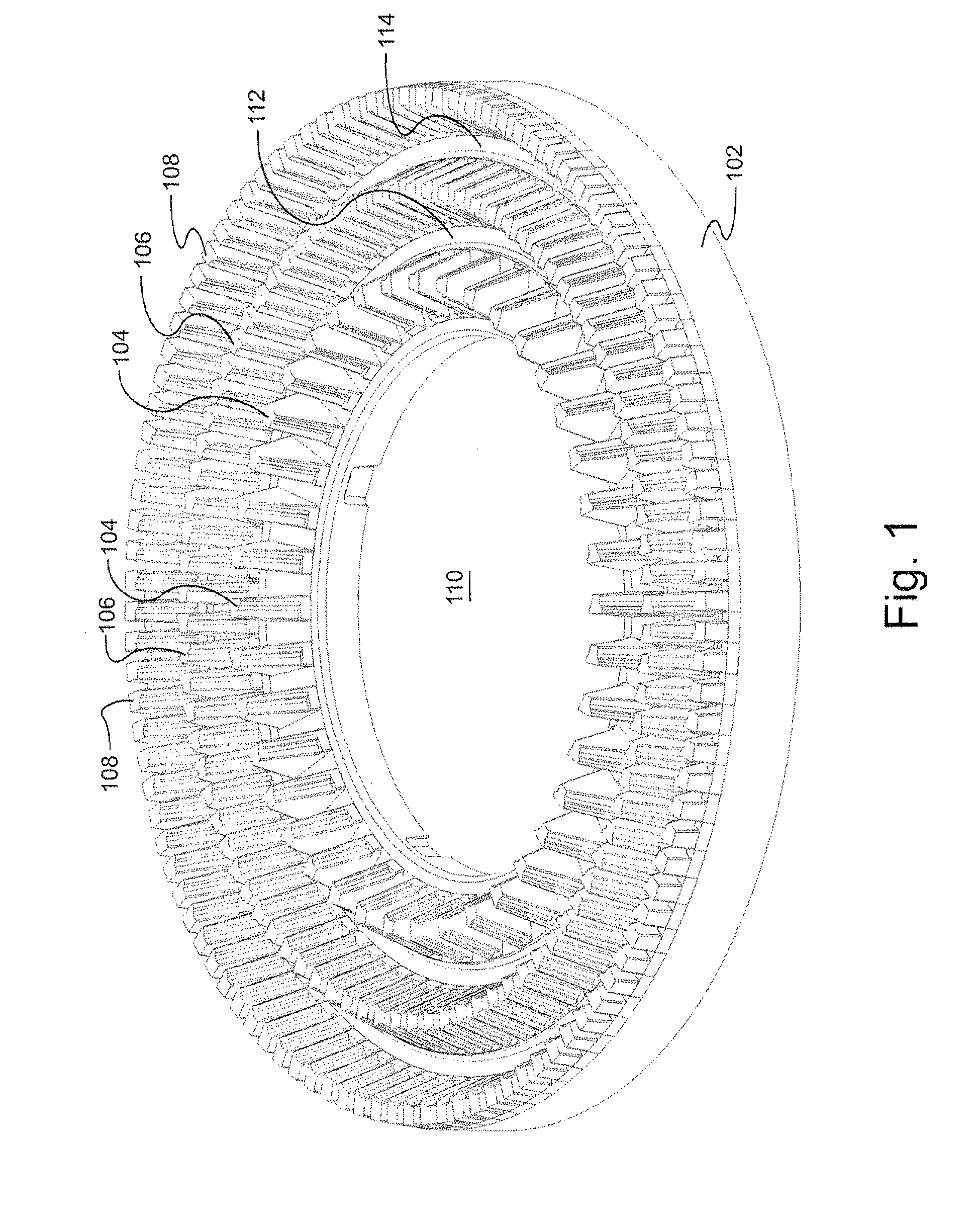
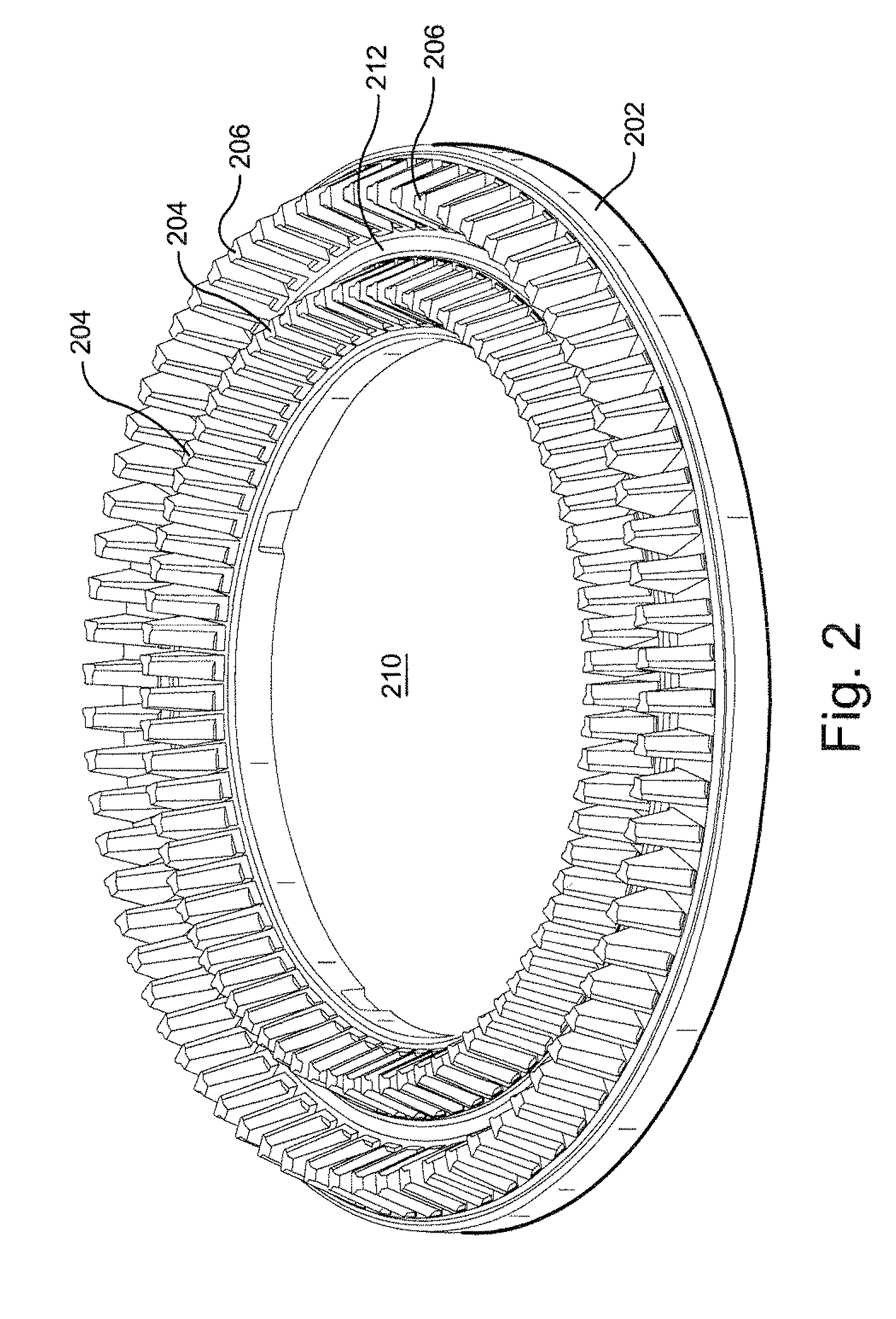
[0024]In an aspect, the invention relates to deflaker plates having surfaces of teeth that are not parallel (and perpendicular) to the axis of plate rotation. For example, the deflaker plates may have teeth that are not substantially cubic and instead are substantially trapezoidal or substantially triangular. That is, the teeth may have leading and trailing faces that each are substantially in the shape of a triangle or trapezoid. These shapes within the scope of certain aspects of the invention may affect the magnitude and direction of the hydraulic impulses during the sweeping process of rotor and stator teeth.

[0025]In certain embodiments, the teeth may form one, two, three, or more (e.g., five or ten) annular rings around each of the rotor and stator plates. Generally, the slurry flows from the center of the plates (which preferably may rotate counter relative to each other and / or, in some embodiments rotate at different frequencies or speeds) to the outer circumference, generall...


PUM

PropertyMeasurementUnit
angleaaaaaaaaaa
angleaaaaaaaaaa
angleaaaaaaaaaa

Abstract

A deflaker plate for use in a deflaker for reducing fibrous flakes in a slurry of fibers. The deflaker plate may include at least one annular ring consisting of multiple teeth, in which at least one tooth has a leading face, a trailing face, and an impact-generating side-face. The impact-generating side-face may be adapted to generate an impact force during operation, such that the force corresponds to a first vector radially pushing the slurry towards a center of the deflaker and a second vector tangentially pushing the slurry towards the leading face.

Description

[0001]This application claims the benefit of priority to U.S. App. No. 61 / 172,092 filed on Apr. 23, 2009, the contents of which are incorporated herein by reference.BACKGROUND OF THE INVENTION[0002]This invention generally relates to systems and methods for flake reduction in fibrous materials. For example, the present invention may have particular applicability in the disintegration of fiber bundles in kraft or mechanical pulps and for recycled fibers as well as in flake reduction in broke handling systems.[0003]Turning fibrous material (e.g., lignocellulosic material) or paper (e.g., broke) into individualized fibers generally involves disintegrating fiber mats into fibers under the influence of shear in a suspension environment. This may be accomplished, for example, in a mechanical refiner between two refiner plates. The repeated application of shear in the presence of water allows the fiber mat to dissolve the fibrous compound into smaller and smaller pieces until it has broken...

Claims


Application Information

Patent Timeline
Patent Type & Authority Applications(United States)
IPC IPC(8): D21C9/00D21D5/02B22D25/02
CPCD21D1/30D21D1/008
Inventor ANTENSTEINER, PETER
Owner ANDRITZ INC
Learn More