Light-emitting device and illumination apparatus

a technology of light-emitting devices and illumination apparatuses, which is applied in lighting apparatuses, electroluminescent light sources, light sources, etc., can solve the problems of /b> connected to a higher potential side being erroneously turned, increasing both the size and cost of the apparatus, and achieving the effect of positive removal of the effect of external nois

Inactive Publication Date: 2010-10-28
TOSHIBA LIGHTING & TECH CORP +1
View PDF95 Cites 57 Cited by
  • Summary
  • Abstract
  • Description
  • Claims
  • Application Information

AI Technical Summary

Benefits of technology

[0011]An object of the present invention is to provide a light-emitting device and an illumination apparatus capable of positively removing the effect of an external noise.

Problems solved by technology

Also, in the case where the LED elements 105 of the illumination apparatus having the dimmer function are turned on with a deep (dark) dim light, the problem is sometimes posed that the current flowing into the LED elements 105 due to the common-mode noise may cause a flicker, thereby having an extremely adverse effect on the commercial value.
Thus, the LED elements 105 connected to a higher potential side would be erroneously turned on by the current inflow due to the common-mode noise.
A capacitor of large capacitance, however, increases both the size and cost of the apparatus, and would lead to bulkiness and a high price of the whole illumination apparatus.
In the insulation-type switching transformer, however, a capacitor is inserted between the primary and secondary windings to suppress noises, and therefore, the effect of the common-mode noise cannot be completely eliminated.
Further, the use of the insulation-type switching transformer poses the problem of a bulky and expensive power circuit.

Method used


Image

  • Light-emitting device and illumination apparatus
  • Light-emitting device and illumination apparatus
  • Light-emitting device and illumination apparatus

Examples


first embodiment

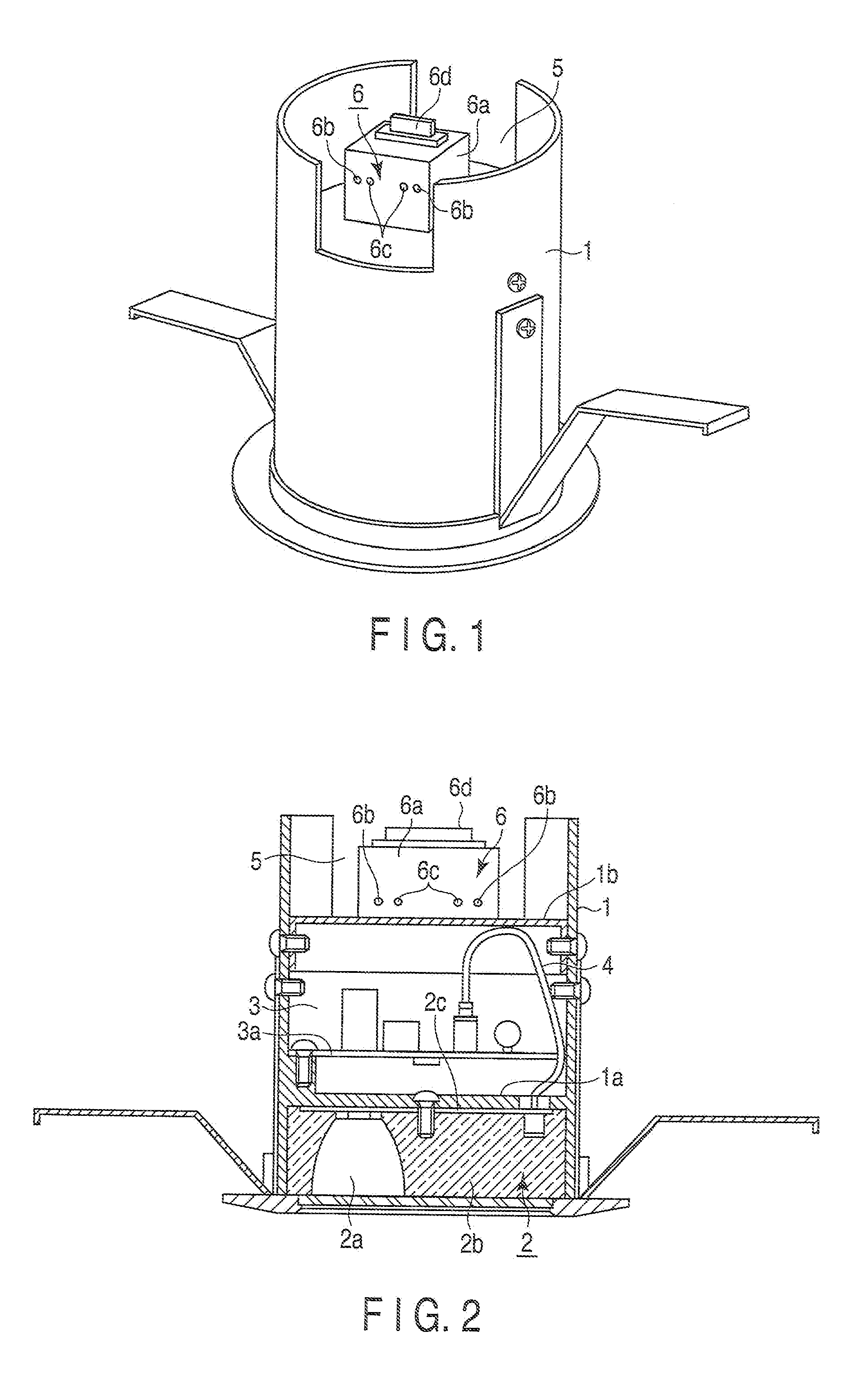
[0043]First, an illumination apparatus according to the present invention is briefly explained. In FIGS. 1 and 2, a housing 1 of the apparatus proper is formed of die-cast aluminum and in the shape of a cylinder open at both ends thereof. The interior of the housing 1 is divided vertically into three parts by partitioning members 1a and 1b, and the space between the lower opening and the partitioning member 1a is formed in a light source unit 2. The light source unit 2 includes a plurality of LEDs 2a as semiconductor light-emitting elements and a reflector 2b. The plurality of the LEDs 2a are arranged and mounted equidistantly along the circumference of a discal wiring board 2c arranged on the lower surface of the partitioning member 1a.

[0044]The space between the partitioning members 1a and 1b of the housing 1 is formed in a power chamber 3. The wiring board 3a is arranged above the partitioning member 1a of the power chamber 3. Electronic parts making up a power circuit to drive ...

first modification

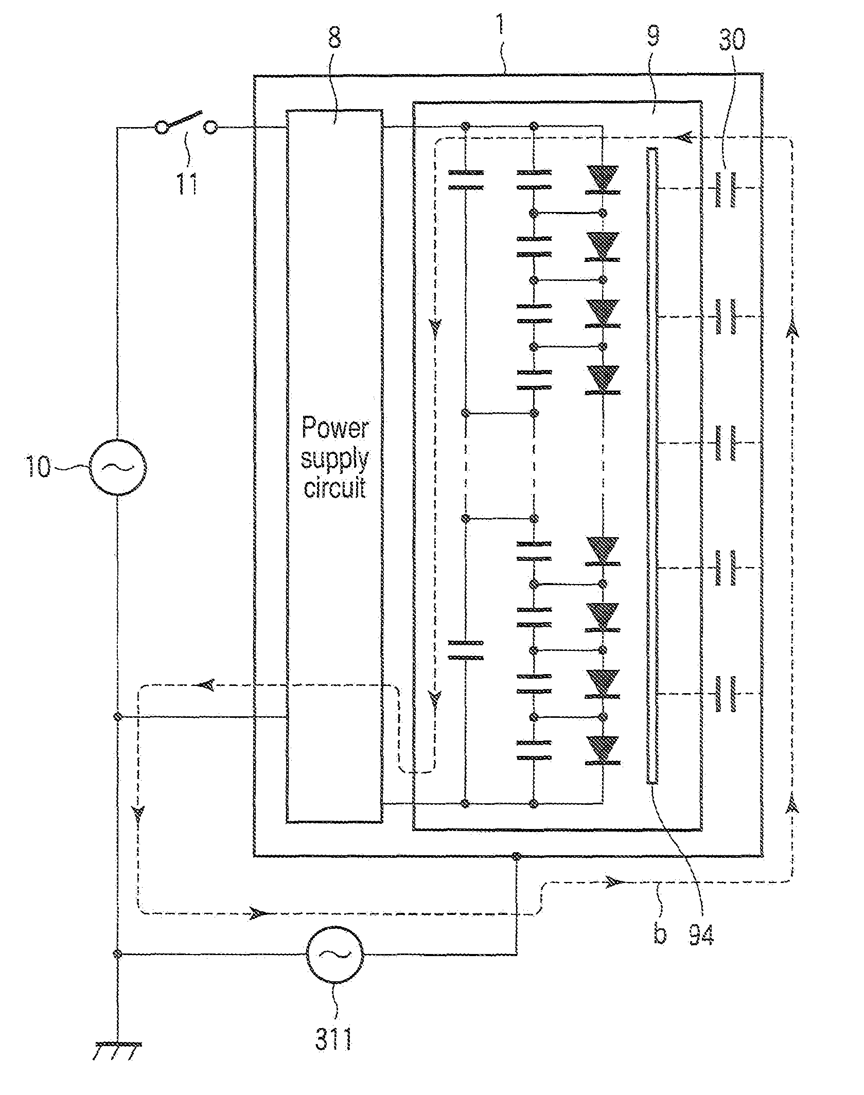
[0064]FIG. 6 shows an LED module according to a modification of the first embodiment described above. In this modification, the LED module 31 is configured of a plurality of (six, in the shown case) LED elements 311a to 311f connected in series, and this series circuit is connected between a positive line 31a and a negative line 31b of the DC power output. The LED elements 311a to 311f are connected in parallel to first bypass capacitors 312a to 312f, respectively. Further, the series circuit of the LED elements 311b to 311f is connected in parallel to a second bypass capacitor 313a, the series circuit of the LED elements 311c to 311f is connected in parallel to a second bypass capacitor 313b and the series circuit of the LED elements 311e and 311f is connected in parallel to a second bypass capacitor 313c. These second bypass capacitors 313a, 313b and 313c have the negative line 31b as a grounding point A1, and with this grounding point A1 as a reference, the AC impedance against t...

second modification

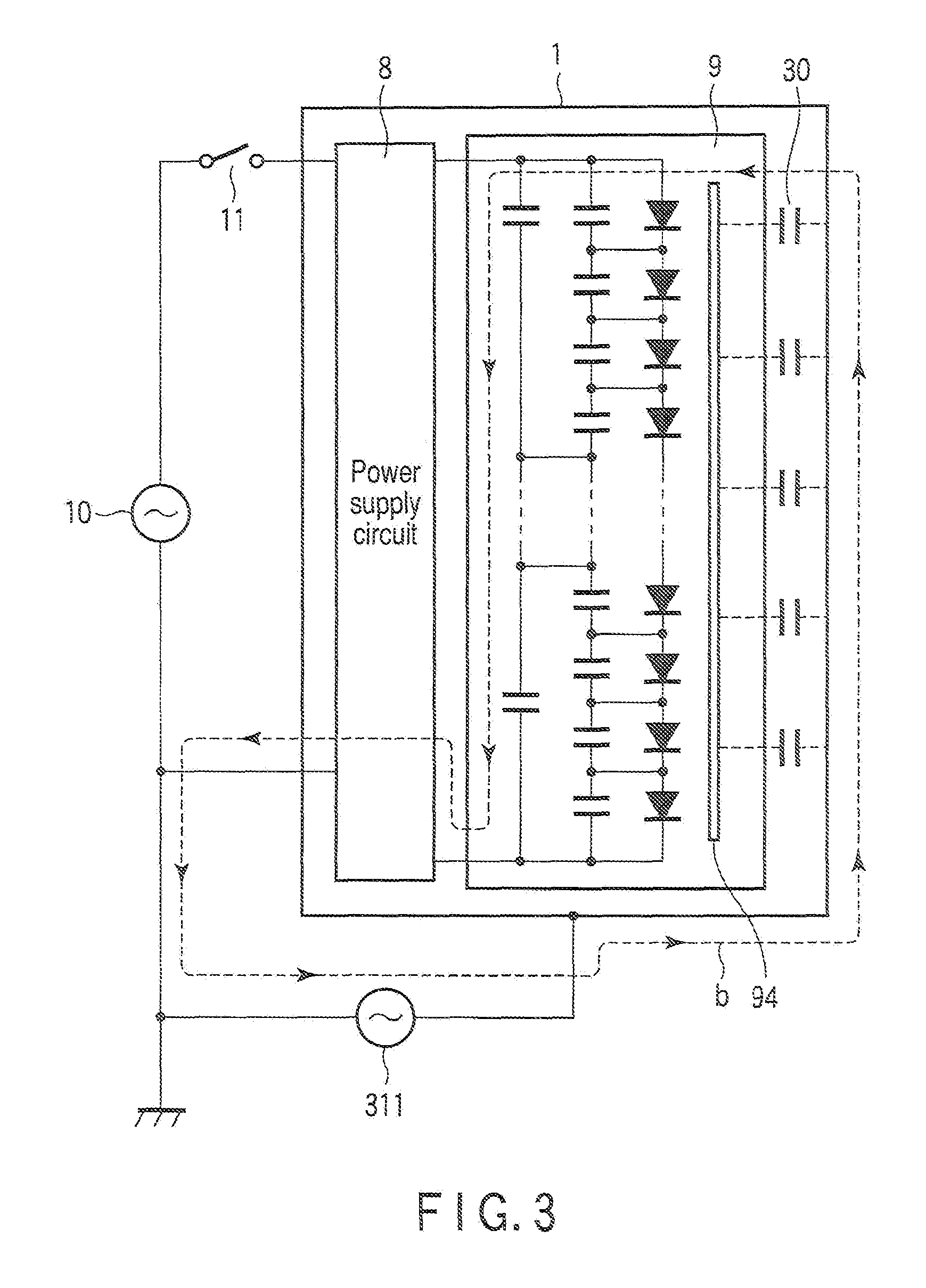
[0066]FIG. 7 shows an LED module according to another modification of the first embodiment.

[0067]In this modification, as shown in FIG. 7, the LED module 32 is configured of a plurality of (six, in the shown case) LED elements 321a to 321f connected in series, and this series circuit is connected between a positive line 32a and a negative line 32b of the DC power output. The LED elements 321a to 321f are connected in parallel to first bypass capacitors 322a to 322f, respectively. Further, the series circuit of the LED elements 321b to 321e is connected in parallel to a second bypass capacitor 323a, and the series circuit of the LED elements 321d and 321e is connected in parallel to a second bypass capacitor 323b. These second bypass capacitors 323a and 323b have the negative line 32b of the LED elements 321a to 321f as a grounding point A2, and with this grounding point A2 as a reference, the AC impedance against the ground at connection points B2, C2, D2 and E2 of the series circui...


PUM


Abstract

A light-emitting device and an illumination apparatus are disclosed. A plurality of LED elements are connected in series between positive and negative lines, and first bypass capacitor is connected in parallel to the LED elements respectively. Each series circuit of a predetermined number of LED elements is connected in parallel to second bypass capacitors. As a result, with the negative power line set as a grounding point, the AC impedance at connection points of the series circuit of the LED elements against the ground is reduced. Thus, the erroneous lighting or “flicker” of each LED which otherwise might be caused by an external noise is prevented.

Description

CROSS-REFERENCE TO RELATED APPLICATIONS[0001]This application is based upon and claims the benefit of priority from prior Japanese Patent Applications No. 2009-106771, filed Apr. 24, 2009; and No. 2010-070543, filed Mar. 25, 2010, the entire contents of both of which are incorporated herein by reference.BACKGROUND OF THE INVENTION[0002]1. Field of the Invention[0003]The present invention relates to a light-emitting device and an illumination apparatus using a semiconductor light-emitting element such as a light-emitting diode (LED element) as a light source.[0004]2. Description of the Related Art[0005]A conventional illumination apparatus which includes a plurality of LED elements connected in series-parallel as disclosed in Jpn. Pat. Appln. KOKAI Publication No. 2008-053695 is available. Also, an illumination apparatus is available which, as shown in FIG. 17, comprises a power circuit 101 and an LED module 102 constituting a light-emitting device in a housing 100 of the illuminatio...

Claims


Application Information

Patent Timeline
Patent Type & Authority Applications(United States)
IPC IPC(8): H05B37/02H05B44/00
CPCH05B33/0803H05B33/0884H05B33/0821H05B45/40H05B45/38H05B45/59
Inventor OTAKE, HIROKAZUHIRAMATSU, TAKUROTERASAKA, HIROSHINISHIIE, MITSUHIKONAKAJIMA, HIROMICHIKAMATA, MASAHIKO
Owner TOSHIBA LIGHTING & TECH CORP
Why Eureka
Try Eureka