Transverse connectors

a technology of transverse connectors and connectors, applied in the field of transverse connectors, can solve problems such as degenerative changes in bones, spine instability, pain and instability,

Active Publication Date: 2010-10-28
SPINAL ELEMENTS INC
View PDF104 Cites 95 Cited by
  • Summary
  • Abstract
  • Description
  • Claims
  • Application Information

AI Technical Summary

Benefits of technology

[0012]The above embodiments and methods of use are explained in more detail below.

Problems solved by technology

Advancing age, as well as injury, can lead to degenerative changes in the bones, discs, joints and ligaments of the spine, producing pain and instability.
Spine instability may result from causes such as fracture, scoliosis and spondylolisthesis, where one or more vertebrae move in a forward direction relative to the other vertebrae.
However, due to variations in body geometries and implanting inconsistencies, the elongate members are rarely parallel in practice.
This solution is not optimal because it introduces misalignments that possibly compromise the strength and stability of the assembly.
Additionally, it could weaken the mechanical properties of the elongate member or the transverse connector.
The disadvantage with this invention is the number of separable pieces, which are difficult to assemble in the clinical environment, especially considering the miniature sizes of some of the pieces.
Surgeons may also risk losing pieces within the patient's body cavity during implantation.
However, the disadvantage of this design is the complexity of the additional screw.
Also, the additional weight and bulk of the hinge joint is another drawback of the design.
Any tiny additional weight or bulk of the fixation assembly can translate into greater discomfort for the patient.

Method used


Image

  • Transverse connectors
  • Transverse connectors
  • Transverse connectors

Examples


Embodiment Construction

[0023]Advancing age, as well as injury, can lead to degeneration in the bones, discs, joints, and ligaments of the spine producing pain from nerve root compression. Under certain circumstances, alleviation of pain can be provided by performing a spinal fusion. Spinal fusion is a procedure that involves joining two or more adjacent vertebrae so that they no longer are able to move relative to each other.

A. Anatomy of the Spine

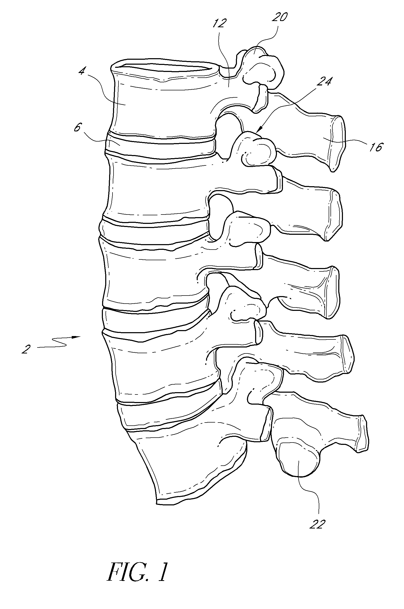
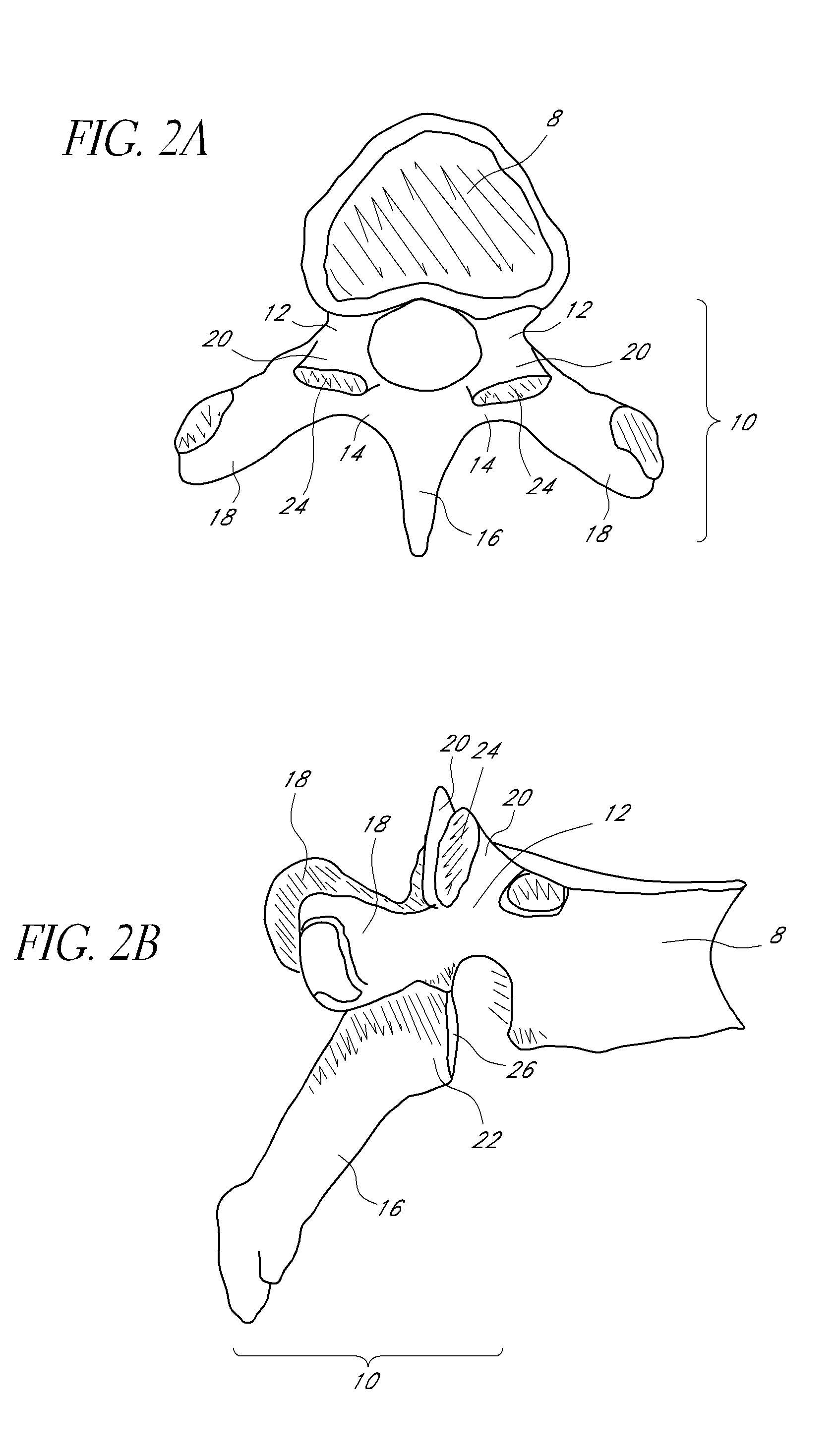
[0024]As shown in FIG. 1, the vertebral column 2 comprises a series of alternating vertebrae 4 and fibrous discs 6 that provide axial support and movement to the upper portions of the body. The vertebral column 2 typically comprises thirty-three vertebrae 4, with seven cervical (C1-C7), twelve thoracic (T1-T12), five lumbar (L1-L5), five fused sacral (S1-S5) and four fused coccygeal vertebrae. FIGS. 2A and 2B depict a typical thoracic vertebra. Each vertebra includes an anterior body 8 with a posterior arch 10. The posterior arch 10 comprises two pedicles 12 and...


PUM


Abstract

Devices and methods are disclosed for treating the vertebral column. One embodiment provides a transverse connector for vertebral fixation systems comprising a first connector body comprising a first engaging member for engaging a first elongate member and a first locking member, a second connector body comprising a second engaging member for engaging a second elongate member, and a transverse rod coupled to the first connector body and the second connector body, thereby forming an articulation between a first end of the transverse rod and the first connector body, wherein the first locking member is configured to secure both the articulation and the first elongate member to the first connector body.

Description

BACKGROUND OF THE INVENTION[0001]1. Field of the Invention[0002]The present invention relates generally to transverse connectors used in spinal fixation systems. The invention comprises assemblies that are coupled to spinal rods, plates, or other elongate members to provide stability to a construct. The invention may be configured so that multiple transverse connectors may be used along the vertebral column.[0003]2. Description of the Related Art[0004]Advancing age, as well as injury, can lead to degenerative changes in the bones, discs, joints and ligaments of the spine, producing pain and instability. Under certain circumstances, alleviation of the problems can be provided by performing spinal fusion. Spinal fusion is a surgical technique where two or more vertebrae of the spinal column are fused together to eliminate the motion between the fused vertebrae. Spinal fusion is used to treat conditions where the spine exhibits instability. Spine instability may result from causes such...

Claims


Application Information

Patent Timeline
Patent Type & Authority Applications(United States)
IPC IPC(8): A61B17/70A61B17/88
CPCA61B17/7052
Inventor BLAIN, JASONMARTIN, GREGHOWARD, STEVEN
Owner SPINAL ELEMENTS INC
Why Eureka
Try Eureka