
Flexible stacking port

a stacking port and flexible technology, applied in the field of stackable network switches, can solve the problems of inflexible chassis-based system configuration, large initial cost associated with purchasing the chassis/backplane, and effectively ‘wasted’ dedicated stacking ports, etc., and achieve the effect of saving the user

Active Publication Date: 2010-11-11
ARRIS ENTERPRISES LLC
View PDF3 Cites 114 Cited by
  • Summary
  • Abstract
  • Description
  • Claims
  • Application Information

AI Technical Summary

Benefits of technology

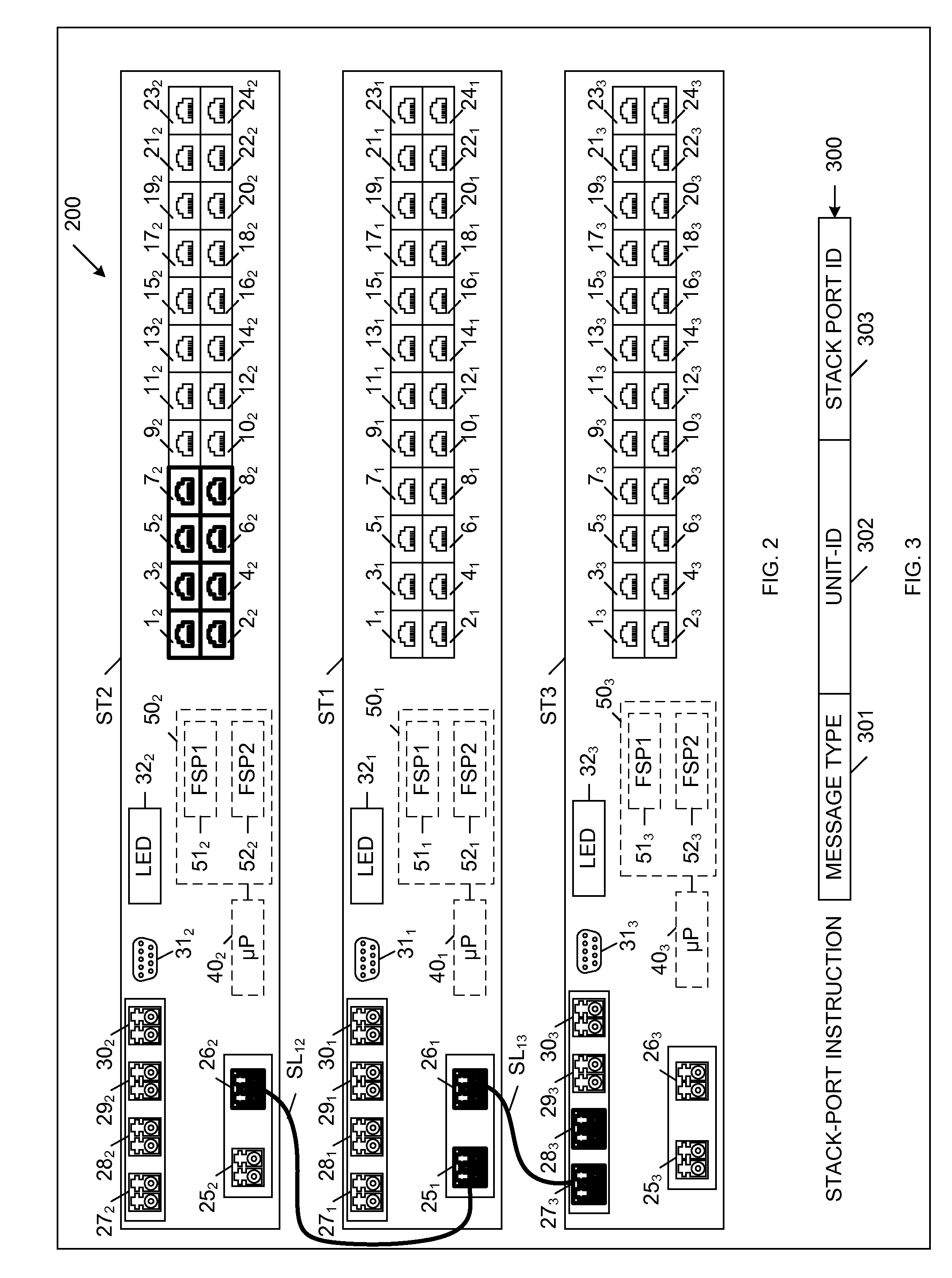
[0006]Accordingly, the present invention includes a stackable device (e.g., network switch) that includes a plurality of ports, each of which can be configured to implement a flexible stacking port or a regular data port. In one embodiment, the stackable device is configured to implement two flexible stacking ports. The ports that are not required to implement the two flexible stacking ports may be used to implement regular data ports. Each of the flexible stacking ports can be used as either a stacking port or a regular data port. Thus, if a flexible stacking port is not configured to operate as a stacking port, it may be used as a regular data port. If a flexible stacking port is a high-bandwidth port, the ability to use this flexible stacking port as regular data port may represent a significant benefit / savings for the user.

Problems solved by technology

The hardwired nature of the backplane and the fixed slot numbers cause the configuration of the chassis-based system to be inflexible.
Another disadvantage of the chassis-based system is the relatively large initial cost associated with purchasing the chassis / backplane.
These two unused dedicated stacking ports are effectively ‘wasted’, because these stacking ports are dedicated to performing a stacking function, and cannot be used for any other purpose.
That is, these dedicated stacking ports cannot be used for carrying regular data traffic.
As a result, the user undesirably pays for hardware that cannot be used.
Consequently, the dedicated stacking ports are relatively expensive.

Method used


Image

  • Flexible stacking port
  • Flexible stacking port
  • Flexible stacking port

Examples


Embodiment Construction

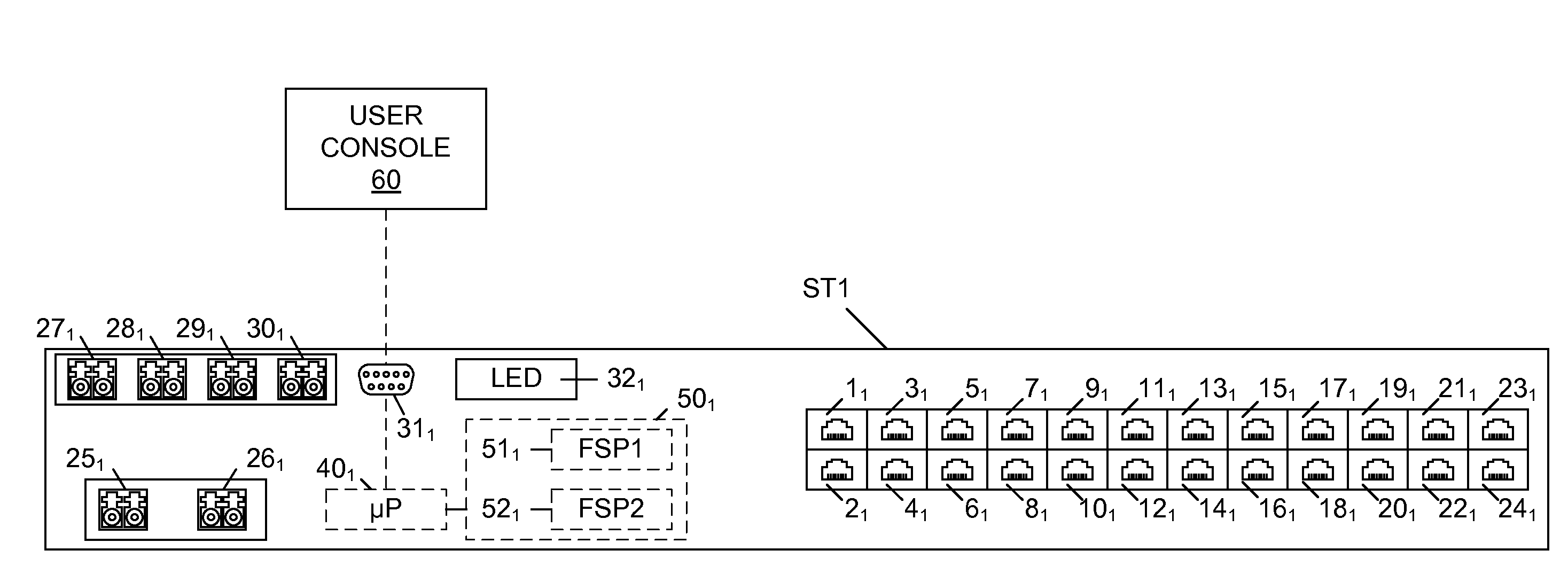
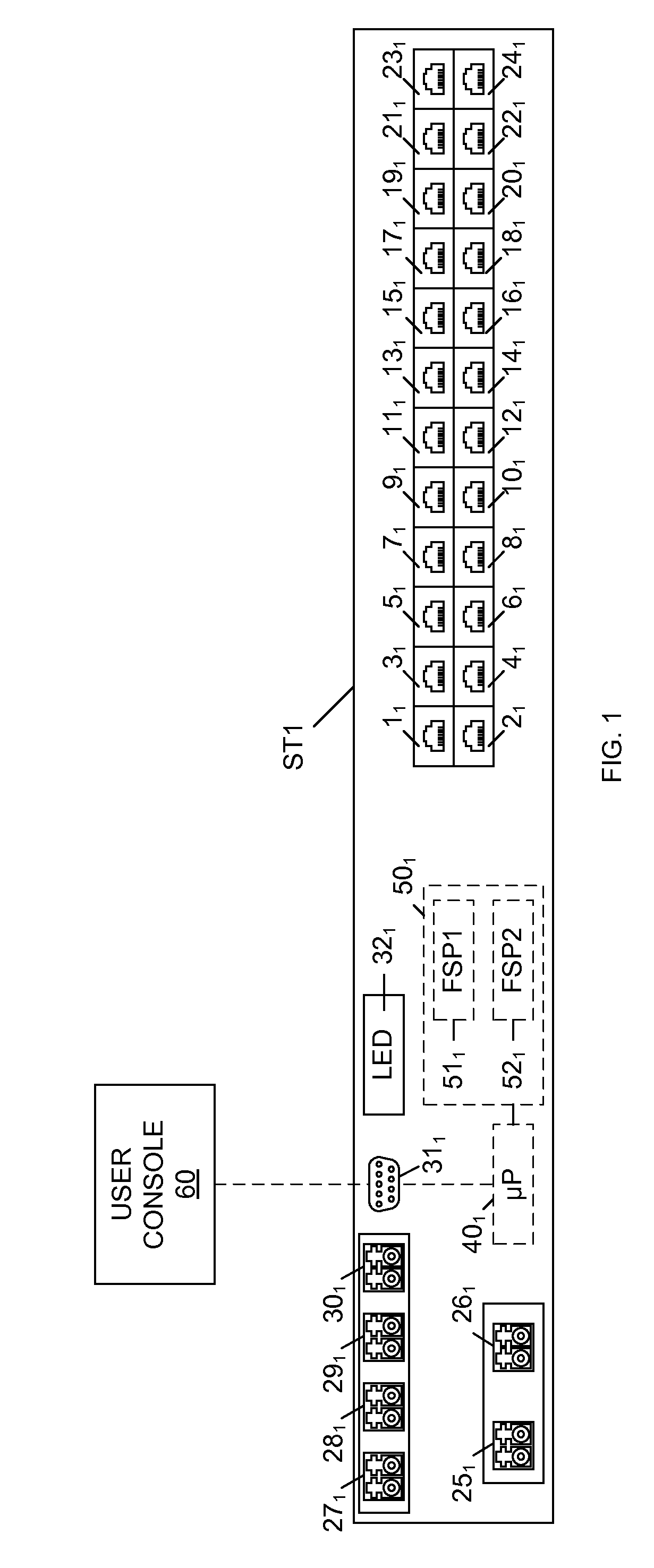
[0015]FIG. 1 is a block diagram of a stackable device (network switch) ST1 in accordance with one embodiment of the present invention. Stackable device ST1 includes 10 / 100 / 1000 Mb ports 11-241, 10 Gb ports 251-301, direct serial interface 311, LED display 321, processor 401 and memory 501 (which includes registers 511 and 521). Each of ports 11-241 includes a copper-based module capable of transferring data at up to 1 Gigabit per second (Gbps) (full-duplex), and each of ports 251-301 includes a fiber-based module capable of transferring data at speeds up to 10 Gbps (full-duplex). Because of their relative data transfer speeds, ports 11-241 may be referred to as low-bandwidth ports, and ports 251-301 may be referred to as high-bandwidth ports. Although stackable device ST1 includes 24 low-bandwidth ports and six high bandwidth ports, it is understood that stackable device ST1 may have other numbers of ports in other embodiments. In one embodiment, low-bandwidth ports 11-241, high-ban...


PUM


Abstract

A stackable device having a plurality of data ports, wherein each of the data ports is capable of operating as a regular data port or a stacking port. A first set of one or more of the data ports is specified as a first flexible stacking port, and a second set of one or more of the data ports is specified as a second flexible stacking port. Each flexible stacking port can be individually configured to operate as an actual stacking port, if required by the configuration of an associated stack. If a flexible stacking port is not configured to operate as an actual stacking port, then the data port(s) included in the flexible stacking port are available to operate as regular data port(s).

Description

FIELD OF THE INVENTION[0001]The present invention relates to a stackable network switch having flexible ports that can be configured as either stacking ports or regular data ports.RELATED ART[0002]Local area networks (LANs) may be implemented using a chassis-based system, which includes a fixed chassis that supports a common backplane (i.e., a hardwired circuit board). The fixed chassis includes a plurality of slots for receiving and supporting a plurality of network switches (blades). When inserted into the slots in the chassis, connectors on the network switches engage with corresponding connectors in the backplane, whereby electrical connections are formed between the network switches and the backplane. The backplane provides electrical connections between the connected network switches, and allow the plurality of network switches to be operated as a single management unit. A slot number is assigned to each connector in the backplane in order to identify the placement of each net...

Claims


Application Information

Patent Timeline
IPC IPC(8): H04L12/56
CPCH04L49/351H04L49/45H04L49/15H04L63/08H04L49/65
Inventor AGARWAL, BIPINLAVINE, MARCLIN, KEVIN KWUN-NANMURTINTY, RAJESHEKHAR
Owner ARRIS ENTERPRISES LLC
Learn More