Identifying RFID categories

a radio frequency identification and category technology, applied in the field of digital communication, can solve the problems of inability of the reader to determine how many tags he or she receives, the inability of the reader to state with certainty which tags are in the system, and the inability of the reader to identify the particular tags that are transmitting during the slo

Active Publication Date: 2010-11-25
ALCATEL LUCENT SAS
View PDF42 Cites 9 Cited by
  • Summary
  • Abstract
  • Description
  • Claims
  • Application Information

AI Technical Summary

Benefits of technology

[0017]In yet another embodiment, the invention is a reader for an RFID system further comprising one or more tags, the reader comprising a processor and an antenna. The processor is adapted to generate a downlink signal, and the antenna is adapted to transmit the downlink signal to the one or more tags and receive one or more uplink signals from the one or more tags. The processor is further adapted to process the one or more uplink signals. The downlink signal comprises a multiplicity value indicating a number of slots, such that a tag that transmits an uplink signal in response to receipt of the downlink signal will (1) select two or more different slots in a multi-slot frame based on the multiplicity value and (2) transmit the

Problems solved by technology

A potential problem with the interrogation procedure is collisions, i.e., when two or more tags transmit at the same time.
A reader that receives a collision typically cannot determine how many tags transmitted to generate the collision, or wh

Method used


Image

  • Identifying RFID categories
  • Identifying RFID categories
  • Identifying RFID categories

Examples


Embodiment Construction

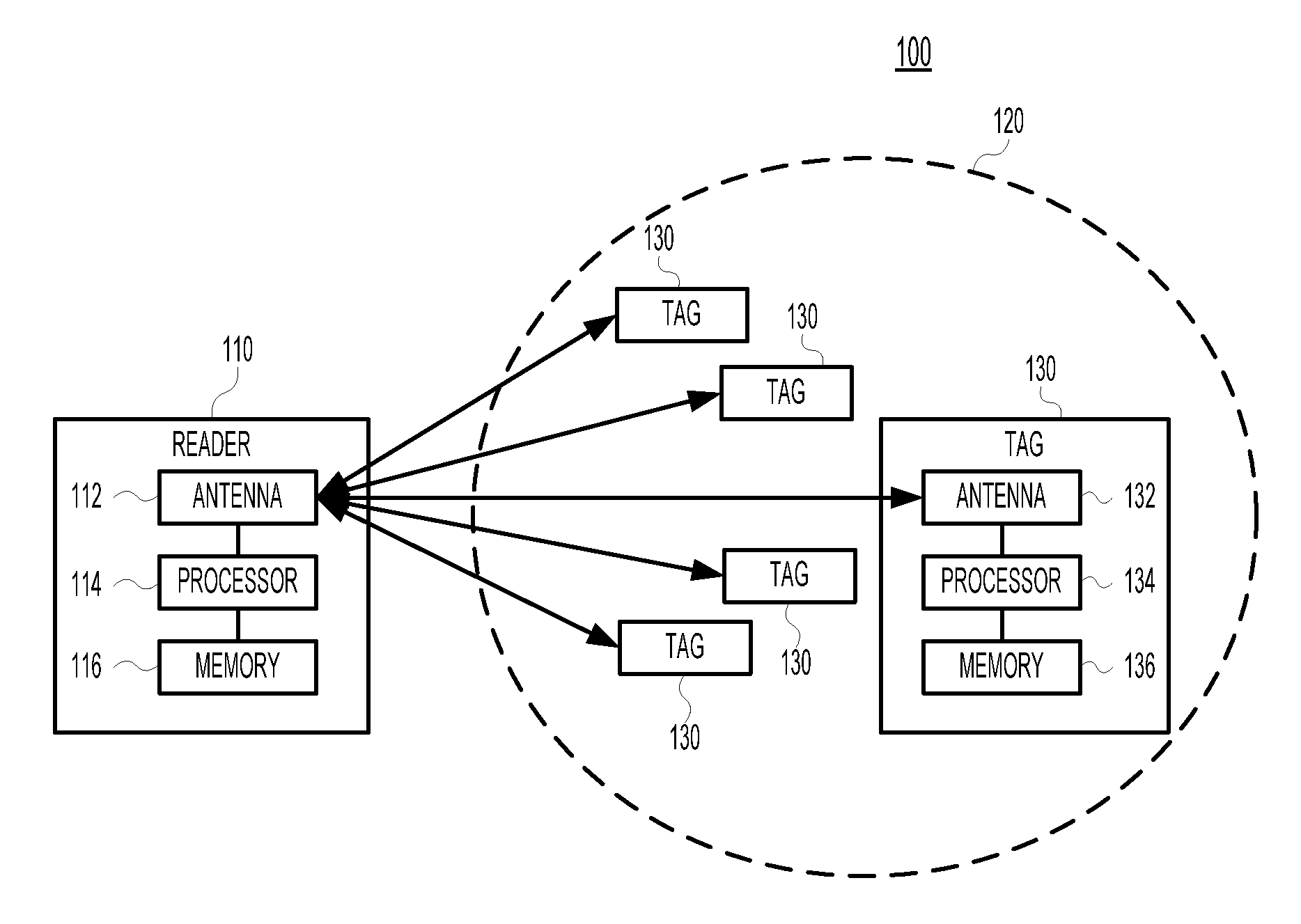
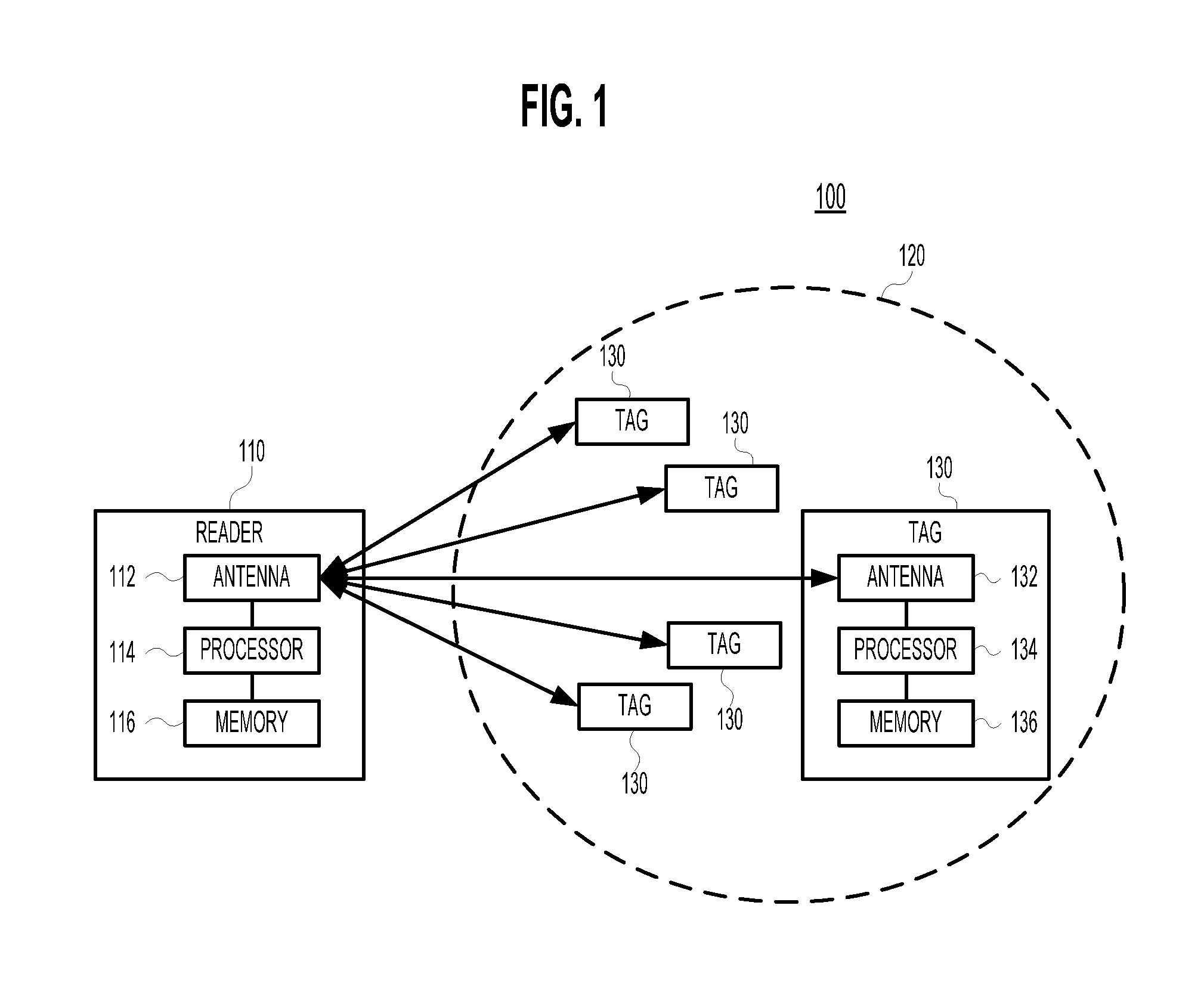
[0024]The set of all possible tag categories is denoted N, and the number of distinct categories in set N, i.e., the cardinality of set N, is denoted n. The set of distinct categories currently present in a particular RFID system is denoted T, and the number of distinct categories in set T, i.e., the cardinality of set T, is denoted t. It is assumed that set N and cardinality n are known quantities, and that cardinality t can be estimated. One method for estimating cardinality t can be found in U.S. patent application Ser. No. 11 / 525,339 filed on Sep. 22, 2006 as attorney docket no. Kodialam 46-9, which application is herein incorporated by reference in its entirety.

[0025]Various embodiments of the present invention are systems and methods for efficiently determining, with probability greater than 1−∈, where 0<∈<1, the set T of distinct categories present in an RFID system. In other words, on average, out of 1 / ∈ interrogations to identify set T, no more than one interrogation should...


PUM


Abstract

The set T of all categories in a population of RFID tags is estimated within a specified error bound. For each of one or more frames, a reader broadcasts a probability p, a multiplicity d, a frame size M, and a seed value R to the present tags. A deterministic algorithm on each tag, and known to the reader, calculates (i) whether the tag will transmit in this frame, and, if so, (ii) in which slots the tag will transmit a single “1.” When the tags have responded, the reader calculates set T by initially assuming that all possible categories are in set T and then eliminating those categories that would have transmitted in those slots in which no tag transmitted. Alternatively, the reader initially assumes that set T is empty, and adds those categories that would have transmitted in those slots in which one or more tags did transmit.

Description

BACKGROUND OF THE INVENTION[0001]1. Field of the Invention[0002]The invention relates to digital communication, and more specifically to Radio Frequency Identification (RFID).[0003]2. Description of the Related Art[0004]Advances in supply-chain technologies are promoting the rapid deployment of RFID tags to identify individual items, such as passports, retails products, books, or even humans.[0005]FIG. 1 is a block diagram of conventional RFID system 100. RFID system 100 comprises reader 110 and one or more RFID tags 130 that are within the interrogation zone 120 of reader 110.[0006]Reader 110 comprises an antenna 112, a processor 114, and a memory 116. A typical tag 130 comprises (i) an antenna 132, (ii) a memory 136, and (iii) a processor 134 for rudimentary calculations. FIG. 1 shows details for only one tag, but each tag comprises the same components. A typical tag contains within its memory a unique 12-digit hexadecimal tag identifier (tag ID), comprising an 8-digit hexadecimal...

Claims


Application Information

Patent Timeline
IPC IPC(8): H04Q5/22
CPCG06K7/10059G06K7/0008
Inventor KODIALAM, MURALINANDAGOPAL, THYAGALAU, WING C.
Owner ALCATEL LUCENT SAS
Why Eureka
Try Eureka