Front consumables for pulse gmaw torches

a consumable and pulse gmaw technology, applied in the direction of manufacturing tools, combustion types, lighting and heating apparatuses, etc., can solve the problems achieve the effect of reducing electrical resistance and arc erosion, not contributing to the efficiency of the contact tip, and reducing the size of the contact area

Active Publication Date: 2010-12-16
ILLINOIS TOOL WORKS INC
View PDF17 Cites 16 Cited by
  • Summary
  • Abstract
  • Description
  • Claims
  • Application Information

AI Technical Summary

Benefits of technology

The present invention provides a welding torch retaining head and contact tip that reduces electrical resistance and arc erosion by improving the mechanical contact force of electrode wire against the contact tip. This is achieved by removing an internal portion of the contact tip that provides mechanical support but not the welding current to the electrode wire. The resulting improved mechanical contact between the contact tip and electrode wire reduces fluctuations in the welding arc and arc erosion on the contact tip, improving the stability of electrical conduction and the performance of the contact tip.

Problems solved by technology

The technical problem addressed in this patent text is the deterioration of the contact tip in welding torches during pulse welding applications, caused by the high current and high current ramp rate used in modern waveforms, as well as the wear and tear from the constant contact with the electrode wire. This can lead to lower energy consumption, reduced efficiency of the contact tip, and undesired welding defects such as cold welding and discontinuous beads. The text describes various methods to improve the contact force between the contact tip and electrode wire, but these methods have limitations such as being too expensive or fragile. The patent proposes a new solution to address this problem.

Method used


Image

  • Front consumables for pulse gmaw torches
  • Front consumables for pulse gmaw torches
  • Front consumables for pulse gmaw torches

Examples


Embodiment Construction

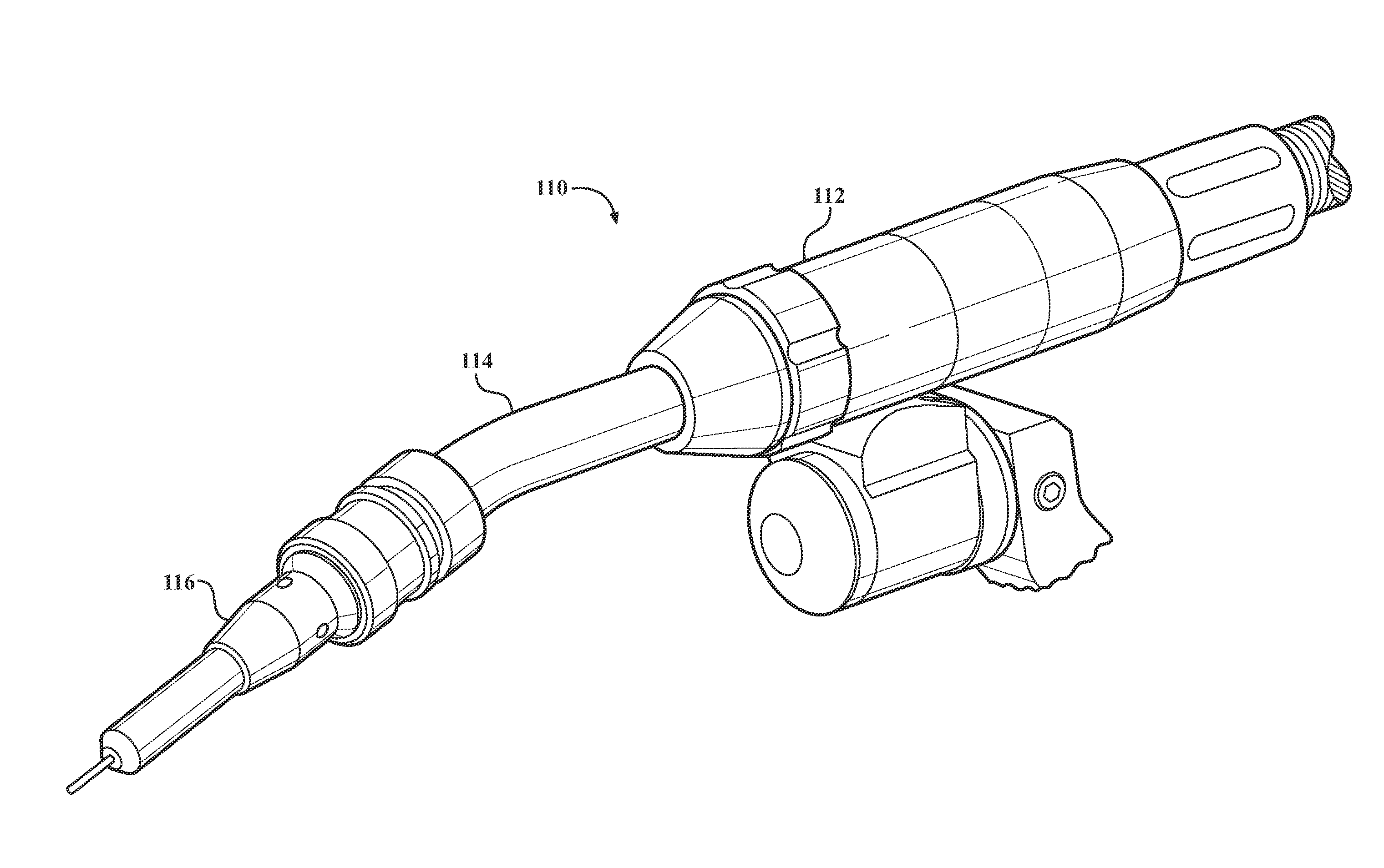
[0035]Referring now to the drawings in detail, numeral 110 generally indicates a welding torch such as a gas metal arc welding (GMAW) torch or a similar welding torch. As shown in FIG. 3, the welding torch 110 broadly includes a torch body 112, a gooseneck 114 extending from a forward end of the torch body, and a contact tip assembly 116 at a distal end of the gooseneck. The contact tip assembly 116 generally includes front consumable components such as a retaining head and contact tip which are discussed in greater detail below. During use of the welding torch 110, the contact tip assembly 116 may be covered and protected by a nozzle. A cable (not shown) is connected to a rear end of the torch body 112. The cable supplies at least one of electrical current, shielding gas, and a consumable electrode wire (e.g., a metal welding wire) to the torch body 112. The electrical current, shielding gas, and consumable electrode wire travel through the torch body 112 to the gooseneck 114 and u...


PUM

PropertyMeasurementUnit
Lengthaaaaaaaaaa
Lengthaaaaaaaaaa
Fractionaaaaaaaaaa

Abstract

A contact tip for a welding torch in accordance with the present invention includes an elongated, generally cylindrical body having a front contact end and an opposite rear retaining end. A central aperture is defined by an inner wall of the body. The aperture extends through the body from an opening at the rear retaining end to an opening at the front contact end. The aperture has a front portion and a wider diameter portion adjacent the front portion. The front portion generally has a length that is shorter than a length of the wider diameter portion. A consumable electrode wire fed through the aperture contacts the inner wall in the front portion but does not contact the inner wall in the wider diameter portion.

Description


Claims


Application Information

Patent Timeline
Owner ILLINOIS TOOL WORKS INC
Why Eureka
Try Eureka