Atomizer and electronic cigarette using the same

a technology of electronic cigarettes and atomizers, applied in the field of electronic cigarettes, can solve the problems of not only affecting the health of smokers, but also the health of others around them, and achieve the effect of reducing the risk of smoking

Active Publication Date: 2011-01-20
SHENZHEN SMOORE TECH LTD
View PDF8 Cites 648 Cited by
  • Summary
  • Abstract
  • Description
  • Claims
  • Application Information

AI Technical Summary

Problems solved by technology

As is well known, smoking is not only harmful to a smoker, but also harmful to other people around him due to passive smoking, which is often referred as secondhand smoking.
In addition, a lit cigarette end may cause a fire if it is not properly extinguished.

Method used


Image

  • Atomizer and electronic cigarette using the same
  • Atomizer and electronic cigarette using the same
  • Atomizer and electronic cigarette using the same

Examples


Embodiment Construction

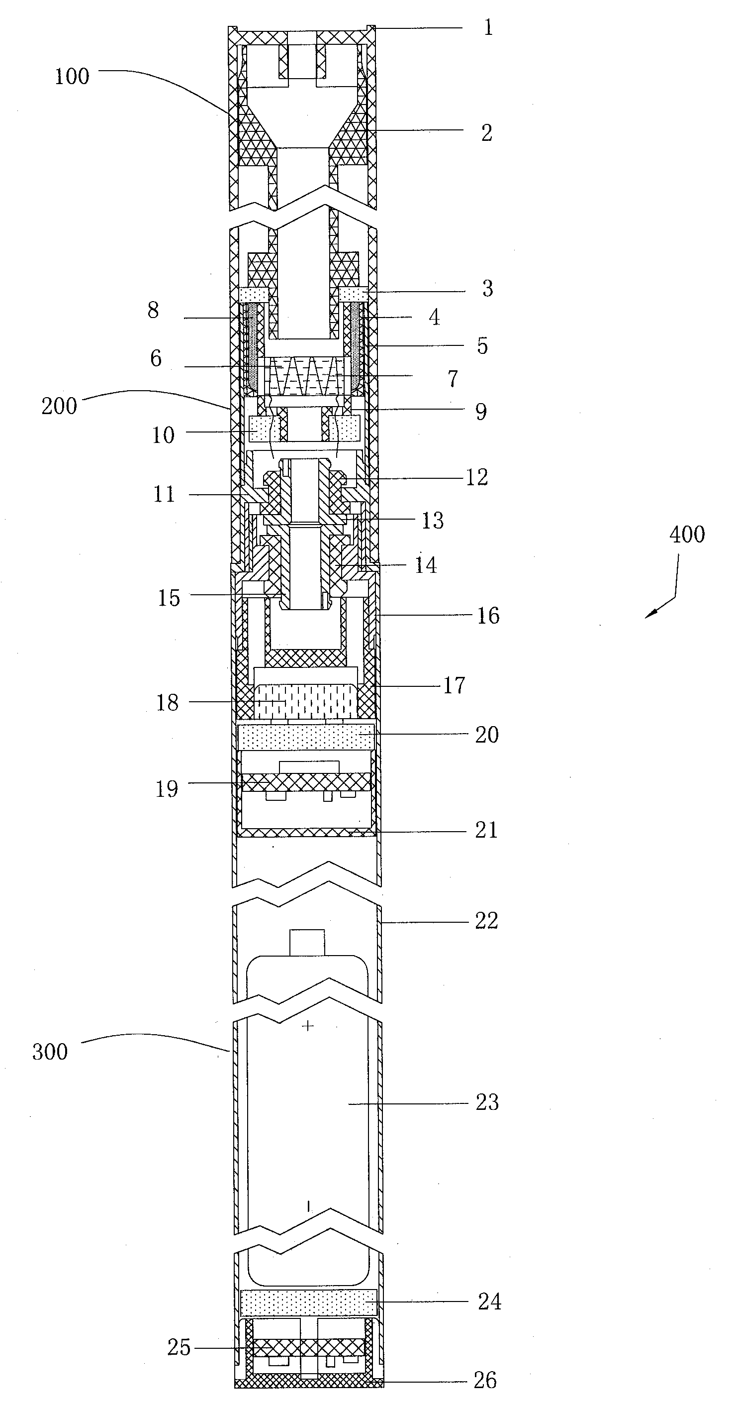
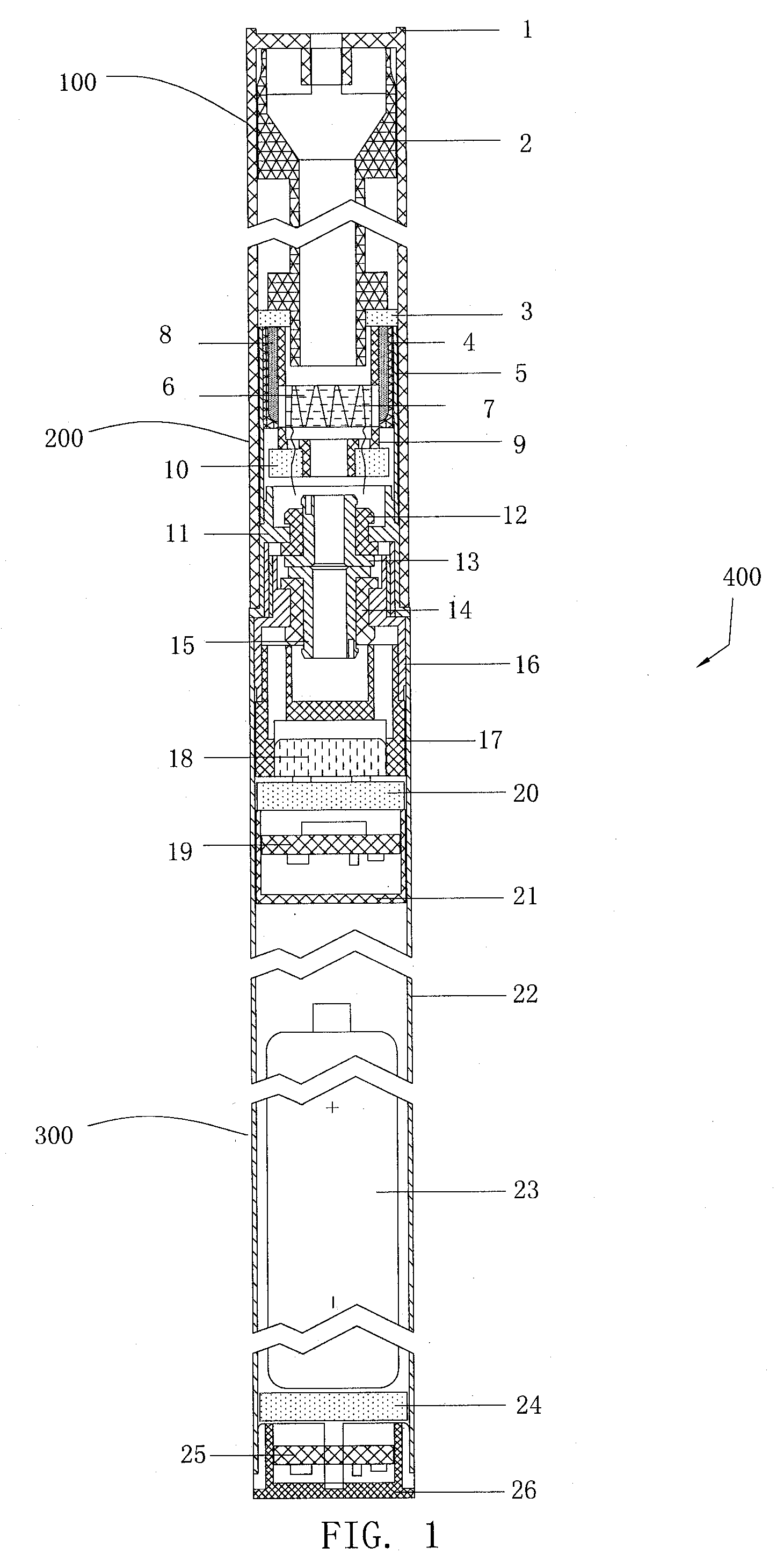
[0012]Referring to FIG. 1, an embodiment of an electronic cigarette 400 includes a container 100 configured for storing a tobacco flavored liquid, an atomizer 200 configured for vaporizing the liquid by electric heating, and a battery tube 300 configured for powering the atomizer 200 and controlling the atomizer 200 to vaporize the liquid. The container 100, the atomizer 200 and the battery tube 300 are connected one by one.

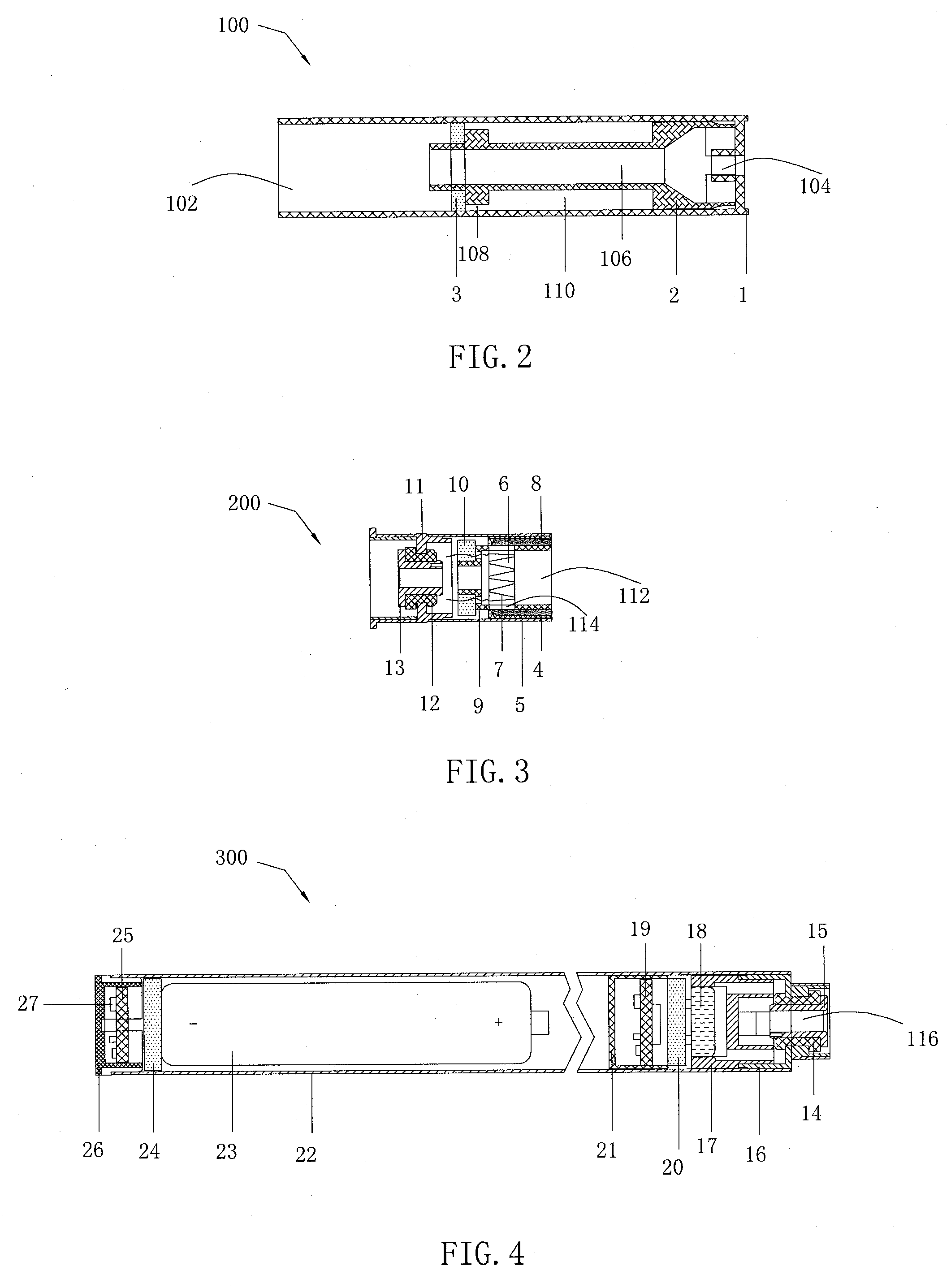
[0013]Referring to FIG. 2, the container 100 is detachably connected to the atomizer 200 to facilitate replacement of the container 100 and the liquid. The container 100 includes an inhalation element 1, a liquid tank 2, and an absorbent element 3. The inhalation element 1 is shaped as a substantially hollow cylinder defining an opening 102 at one end and an inhalation hole 104 at the other end thereof. The liquid tank 2 defines a smoke channel 106 in a middle portion thereof communicating with the inhalation hole 104. The smoke channel 106 has a relative greater...


PUM


Abstract

An electronic cigarette includes a container for storing a tobacco flavored liquid, a container for storing a tobacco flavored liquid, an atomizer connected to the container to atomize the tobacco flavored liquid by an electric heating, a battery tube to power the atomizer, and an actuating film movably positioned in the battery tube to control the atomizer.

Description

BACKGROUND[0001]1. Technical Field[0002]The present disclosure relates to electronic products, and particularly, to an atomizer and an electronic cigarette using the atomizer.[0003]2. Description of Related Art[0004]As is well known, smoking is not only harmful to a smoker, but also harmful to other people around him due to passive smoking, which is often referred as secondhand smoking. In addition, a lit cigarette end may cause a fire if it is not properly extinguished.[0005]Therefore, there is room for improvement within the art.BRIEF DESCRIPTION OF THE DRAWINGS[0006]FIG. 1 is a cross-sectional view of an embodiment of an electronic cigarette.[0007]FIG. 2 is a cross-sectional view of an inhalation element of the electronic cigarette of FIG. 1.[0008]FIG. 3 is a cross-sectional view of an embodiment of atomizer of the electronic cigarette of FIG. 1.[0009]FIG. 4 is a cross-sectional view of a battery tube of the electronic cigarette of FIG. 1.[0010]FIG. 5 is a side, schematic view of...

Claims


Application Information

Patent Timeline
Patent Type & Authority Applications(United States)
IPC IPC(8): A61M15/06A24F40/10A24F40/42A24F40/485
CPCA61M15/06A24F47/008A24F40/10A24F40/42A24F40/485A61M15/0021A61M11/041A61M11/042A61M15/0091A61M11/04A61M15/0095A24F40/40
Inventor FANG, XIAOLIN
Owner SHENZHEN SMOORE TECH LTD
Why Eureka
Try Eureka