Phacoemulsification Needle

Active Publication Date: 2011-01-20
ART LTD
View PDF13 Cites 19 Cited by
  • Summary
  • Abstract
  • Description
  • Claims
  • Application Information

AI Technical Summary

Problems solved by technology

As an example, endothelial cells can easily be damaged during such collapse and this damage is permanent because these cells do not regenerate.
Many surgeons favor phacoemulsifica

Method used


Image

  • Phacoemulsification Needle
  • Phacoemulsification Needle
  • Phacoemulsification Needle

Examples


Embodiment Construction

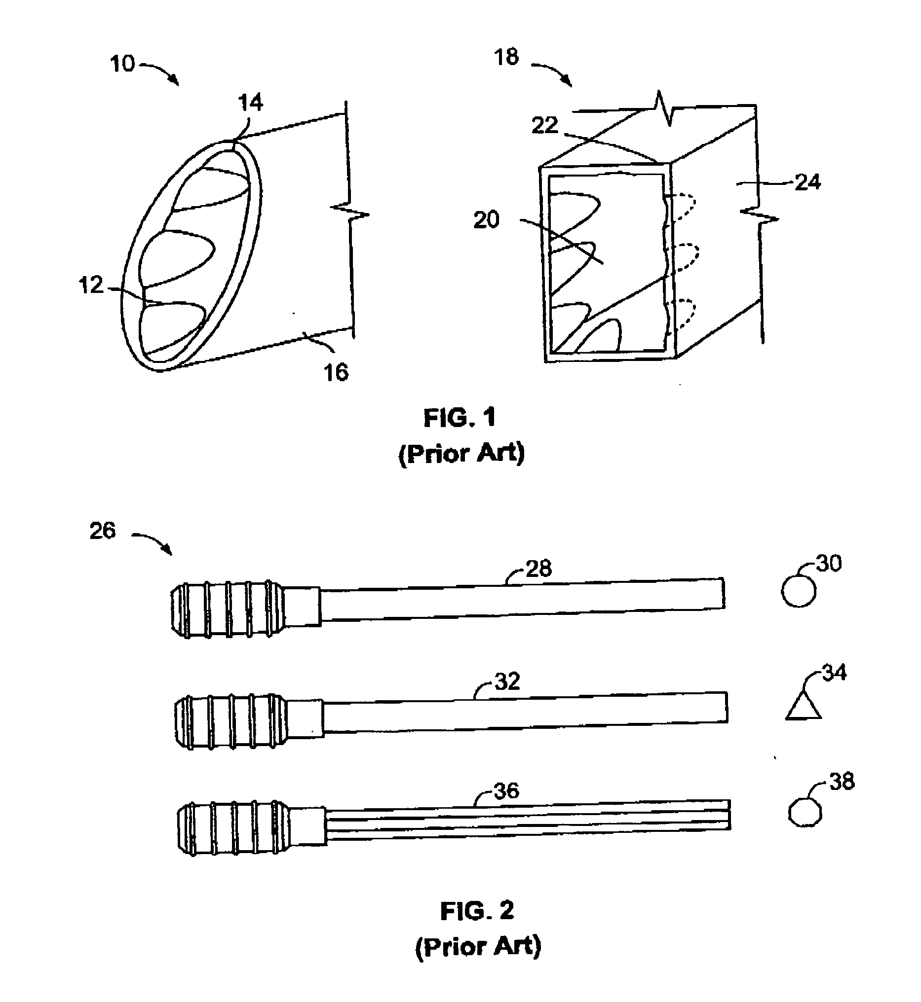
[0053]Referring now to FIG. 1, the numeral 10 indicates generally a prior art phacoemulsification needle tip as shown in U.S. Pat. No. 6,007,555. Needle 10 terminates in a mouth 12 defined by a lip 14 at the end of needle body 16, with lip 14 and needle body 16 formed as having an oval cross-section configuration.

[0054]Referring to FIG. 1, the numeral 18 indicates generally a prior art phacoemulsification needle tip from U.S. Pat. No. 6,007,555, having a mouth 20 defined by a lip 22 at the end of needle 24. The cross-sectional configuration of needle 18 and mouth 20 is a rectangle.

[0055]Referring now to FIG. 2, the numeral 26 identifies several prior art phacoemulsification needles as described in U.S. Pat. No. 5,725,495, with needle 28 having a circular cross-section as shown at 30, needle 32 having a triangular cross-section as shown at 34 and needle 36 having an octagonal cross-section as shown at 38.

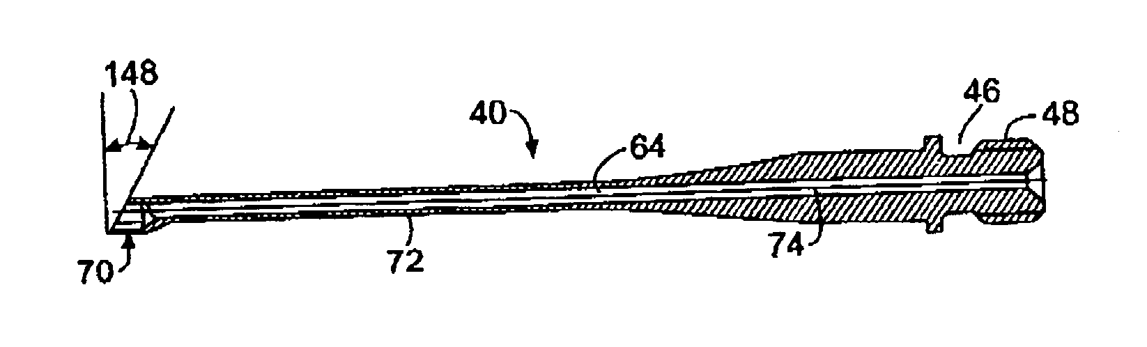
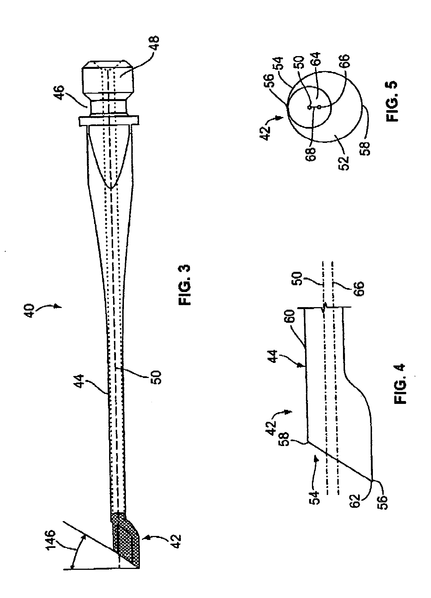
[0056]Both tips 10 and 18 in FIG. 1 exemplify one form of a “straight” needle ti...


PUM


Abstract

A phacoemulsification needle having a hollow passageway terminates in a straight needle tip formed off-axis from the passageway, allowing the needle tip to move eccentrically when the needle is subjected to torsional or longitudinal vibratory motion. The tip may be flared or may be coextensive with the needle body. The aspiration passageway formed through the needle body may be formed off-axis from the needle body axis. The tip may also be angled with respect to the needle body. The inner and outer surfaces of the needle tip are roughened, as by sandblasting, to enhance the cutting effect of the tip when used with a non-longitudinal handpiece. The lip of each needle tip is polished to a high degree of smoothness and the edges of the tip are rounded to lessen the incidence of snags or cuts.

Description

[0001]This application is a continuation-in-part of U.S. patent application Ser. No. 12 / 263,315, filed 31 Oct. 2008, and claims priority from U.S. Provisional Patent Application Ser. No. 61 / 150,320, filed 6 Feb. 2009, both of which are incorporated herein in their entirety by reference.FIELD OF THE INVENTION[0002]This disclosure relates to surgical instruments and surgical techniques used in eye surgery and more particularly, to phacoemulsification apparatus and methods for their use.BACKGROUND OF THE INVENTION[0003]A common ophthalmological surgical technique is the removal of a diseased or injured lens from the eye. Earlier techniques used for the removal of the lens typically required a substantial incision to be made in the capsular bag in which the lens is encased. Such incisions were often on the order of 12 mm in length.[0004]Later techniques focused on removing diseased lenses and inserting replacement artificial lenses through as small an incision as possible. For example, ...

Claims


Application Information

Patent Timeline
IPC IPC(8): A61F9/007
CPCA61B2017/320072A61F9/00763A61F9/00745A61B2017/320096A61B2017/320098
Inventor AKAHOSHI, TAKAYUKI
Owner ART LTD
Why Eureka
Try Eureka