Seal Material

Active Publication Date: 2011-01-27
VALQUA LTD
View PDF26 Cites 21 Cited by
  • Summary
  • Abstract
  • Description
  • Claims
  • Application Information

AI Technical Summary

Benefits of technology

[0017]By the seal material in accordance with the present invention, a sealing property can be satisfactorily maintained in the state in which the seal material is tightened.
[0018]An area of a contact surface of the seal material with the second member is smaller for the sealing part as the contact area is closer to the bottom side of the seal groove, and

Problems solved by technology

At that time, an anchoring fixation may occur between a seal material and a matching sealing surface disadvantageously.
In the case in which a metal seal material is used in

Method used


Image

  • Seal Material
  • Seal Material
  • Seal Material

Examples


Example

EXPLANATIONS OF LETTERS OR NUMERALS

[0027]2: Partial dovetail groove

[0028]2a: Bottom face of a seal groove

[0029]2b: Wall surface on a diameter inward side

[0030]4: Seal material body

[0031]6: Step portion

[0032]8: Separate member

[0033]10: First member

[0034]12: Second member

[0035]S: Curved line

BEST MODE OF CARRYING OUT THE INVENTION

[0036]A seal material in accordance with the present invention will be described below in detail with reference to the drawings.

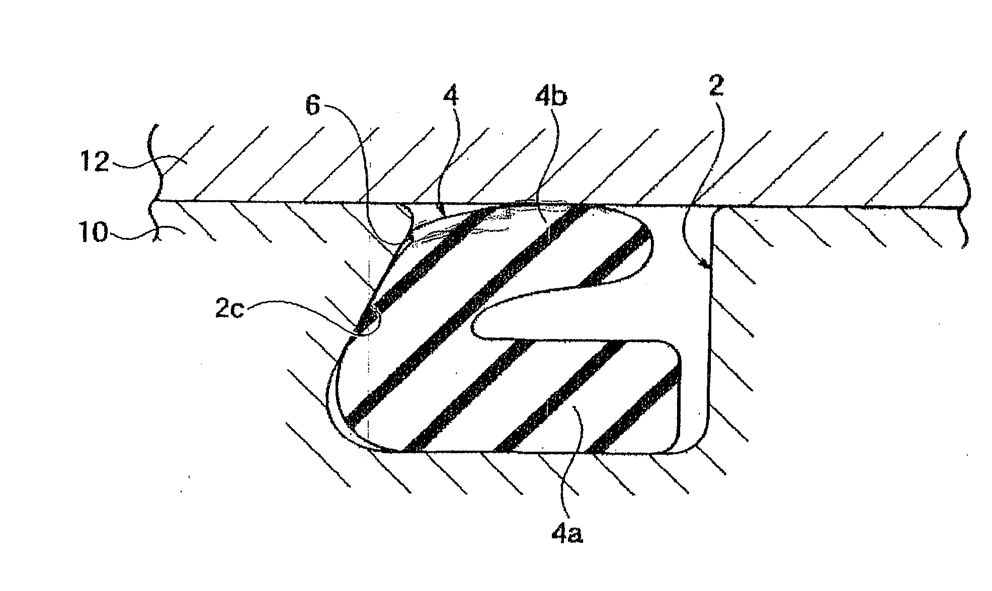
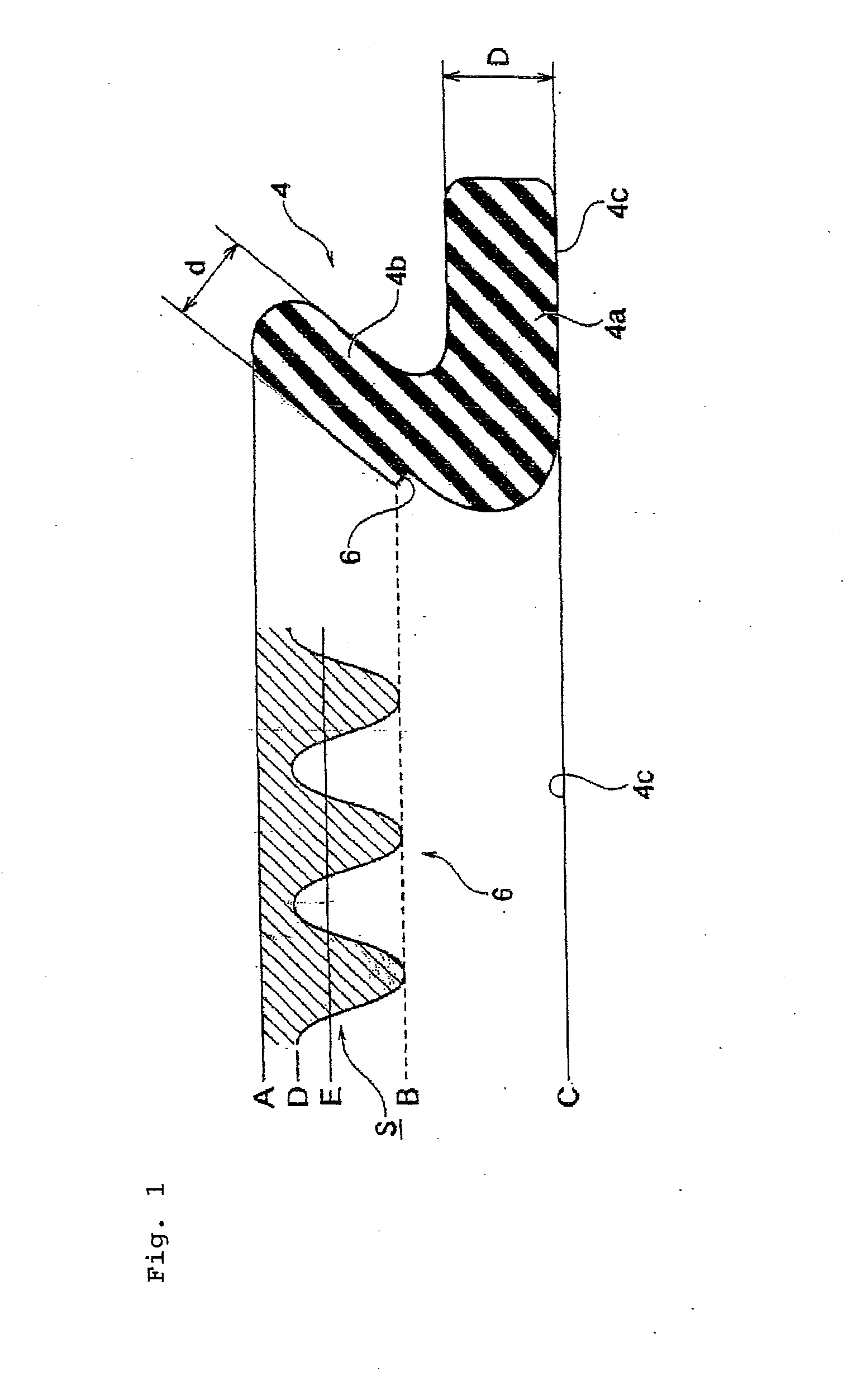
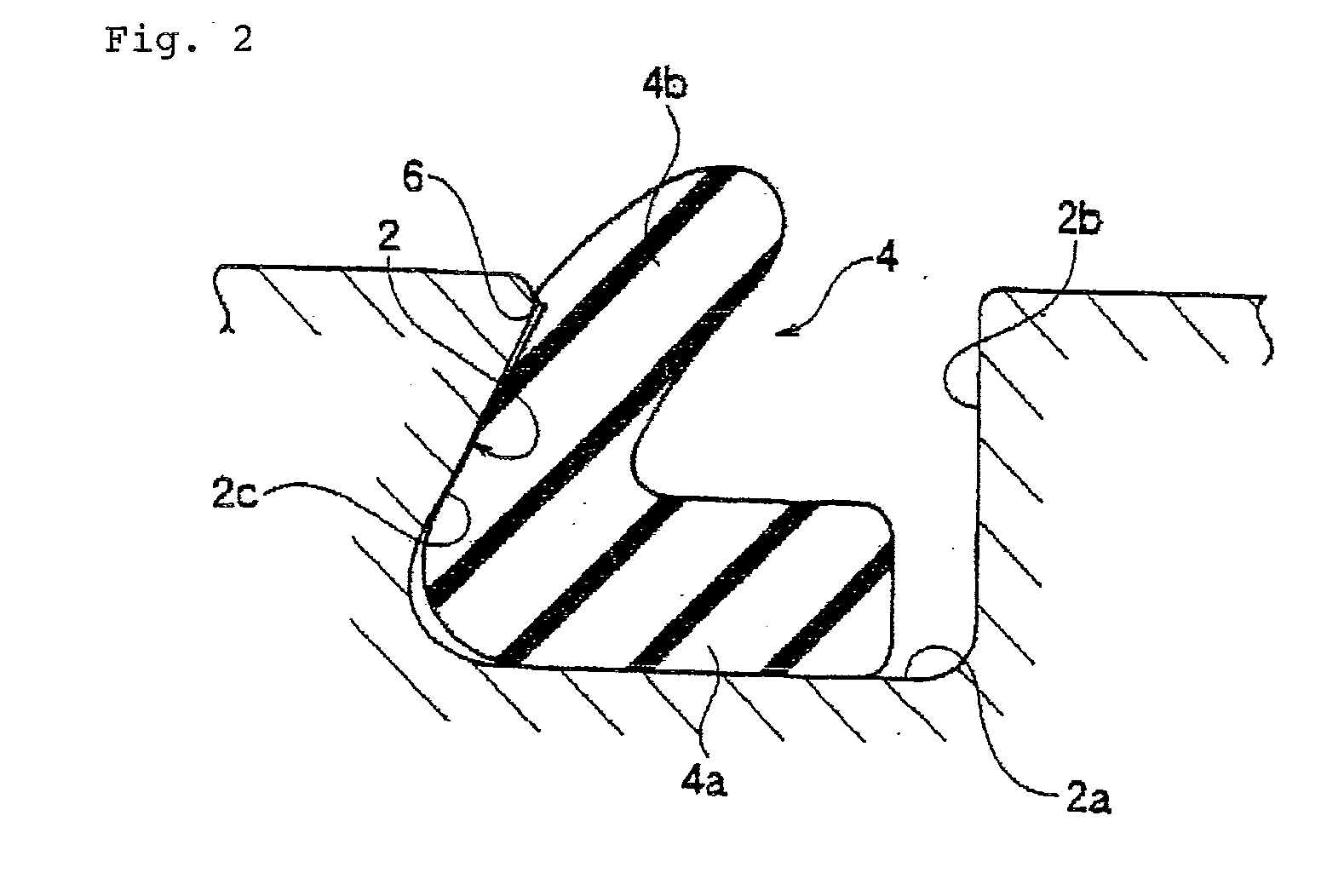
[0037]FIG. 1 shows a seal material 4 in accordance with an embodiment of the present invention. FIG. 2 is a cross-sectional view showing a partial dovetail groove 2 as a seal groove in which the seal material 4 of FIG. 1 is mounted in particular.

[0038]The partial dovetail groove 2 is formed in a coupling joint part of a semiconductor manufacturing apparatus such as a dry etching apparatus and a plasma CVD apparatus. A width of a bottom face 2a of a seal groove is larger than a width of an opening part of the partial dovetail groove 2....


PUM


Abstract

Provided is a seal that can ensure a satisfactory sealing property and can be easily separated from a sealing surface even in the case in which the seal is used for a long period of time under the conditions of a high temperature and a high pressure. The seal includes a seal body mounted in a seal groove that is formed in a first member and a second member is made to be in pressure contact with the first member to form a sealing part. The sealing part that comes into contact with the second member at the entire surface of the sealing part is formed along the entire circumference of the outer peripheral surface of the seal. A step portion is formed on the outer peripheral surface of the seal in such a manner that an area of a contact surface is smaller for the sealing part as the contact area is closer to the bottom side of the seal groove.

Description

TECHNICAL FIELD[0001]The present invention relates to a seal material.BACKGROUND ART[0002]A rubber seal material is extensively used as a general seal material that can easily ensure a sealing property by a low tightening force. For instance, a rubber seal material is used as a seal material for a semiconductor manufacturing apparatus or a gate valve for vacuum in a liquid crystal manufacturing apparatus.[0003]A rubber seal material is in a shape of an O ring or lip packing in a general way. In addition, seals having an irregular cross section that are disclosed in Patent documents 1 to 3 for instance are used in many cases.Patent document 1: Japanese Patent Application Laid-Open Publication No. 10-318373Patent document 2: Japanese Patent Publication No. 3050919Patent document 3: Japanese Patent Application Laid-Open Publication No. 2004-316724DISCLOSURE OF THE INVENTIONPROBLEMS to be Solved by the Invention[0004]A high temperature processing is carried out for a semiconductor manuf...

Claims


Application Information

Patent Timeline
IPC IPC(8): F16J15/06
CPCF16J15/064F16J15/025
Inventor TSUJI, KAZUAKI
Owner VALQUA LTD
Why Eureka
Try Eureka