Filterless and bagless vacuum cleaner incorporating a sling shot separator

a vacuum cleaner and separator technology, applied in the field of floor care equipment, can solve the problems of too much inertia of the large particles in the rotating stream to follow the tight curve of the stream

Inactive Publication Date: 2011-02-03
PANASONIC OF NORTH AMERICA
View PDF24 Cites 54 Cited by
  • Summary
  • Abstract
  • Description
  • Claims
  • Application Information

AI Technical Summary

Benefits of technology

[0004]In accordance with the purposes of the present invention as described herein, a vacuum cleaner is provided comprising a body including (a) a nozzle assembly including a suction inlet and (b) a control assembly. Both a suction generator and a dirt collection vessel are carried on the body. The dirt collection vessel includes a fine particle separator unit having at least one sling shot separator. Each sling shot separator includes a flow channel having an inlet, a debris discharge port and a clean air discharge port. The flow channel also has a radius of curvature of between about 12 mm and about 25 mm and extends in an arc of less than 360° from the inlet to the clean discharge outlet. In one possible embodiment the flow channel extends in an arc of less than 270°. In yet another possible embodiment the flow channel extends in an arc of about 180°. In yet another possible embodiment the flow channel has a radius of curvature of between about 12 mm and about 16 mm.

Problems solved by technology

Specifically, larger particles in the rotating stream have too much inertia to follow the tight curve of the stream.

Method used


Image

  • Filterless and bagless vacuum cleaner incorporating a sling shot separator
  • Filterless and bagless vacuum cleaner incorporating a sling shot separator
  • Filterless and bagless vacuum cleaner incorporating a sling shot separator

Examples


Embodiment Construction

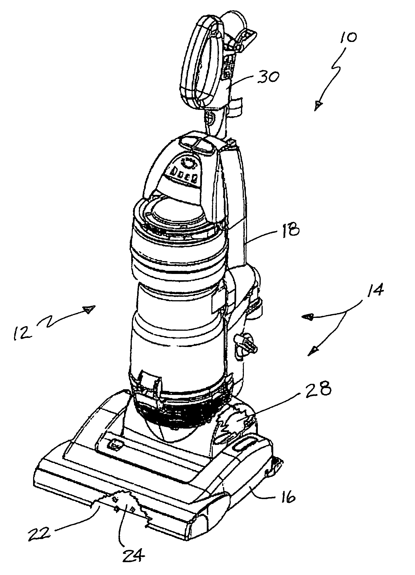
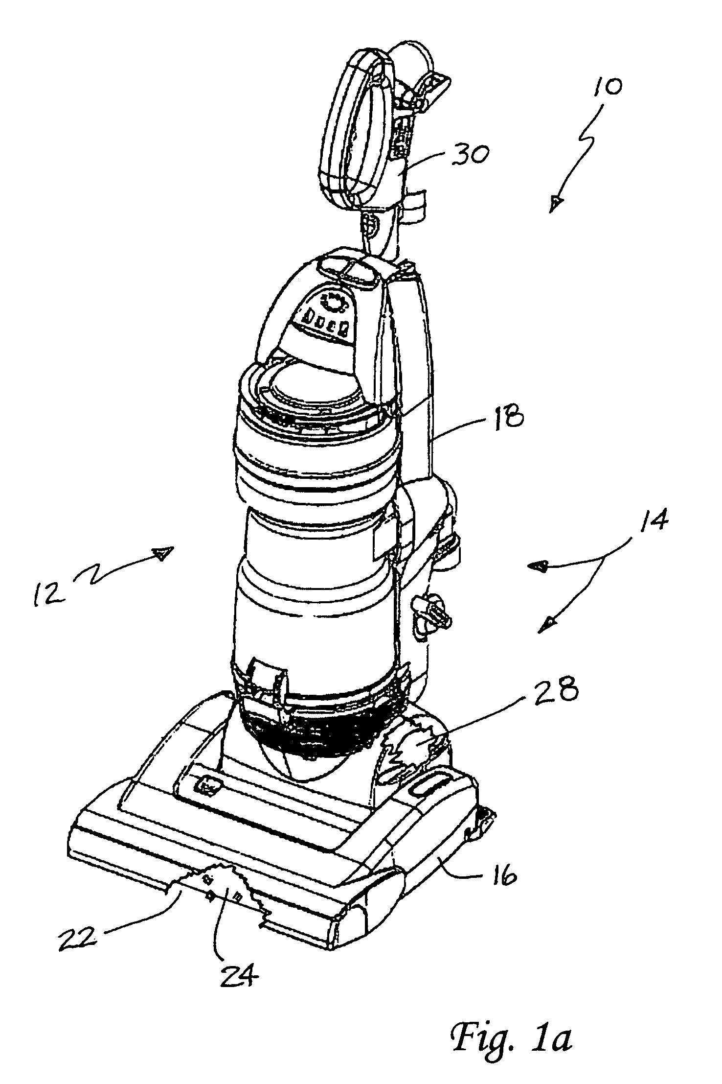
[0019]Reference is now made to FIG. 1 illustrating an upright vacuum cleaner 10 of the present invention. While an upright vacuum cleaner 10 is illustrated, it should be appreciated that the present invention is not limited to upright vacuum cleaners but instead covers any type of vacuum cleaner incorporating the novel dirt collection vessel 12 of the present invention. This includes but is not limited to, canister vacuum cleaners.

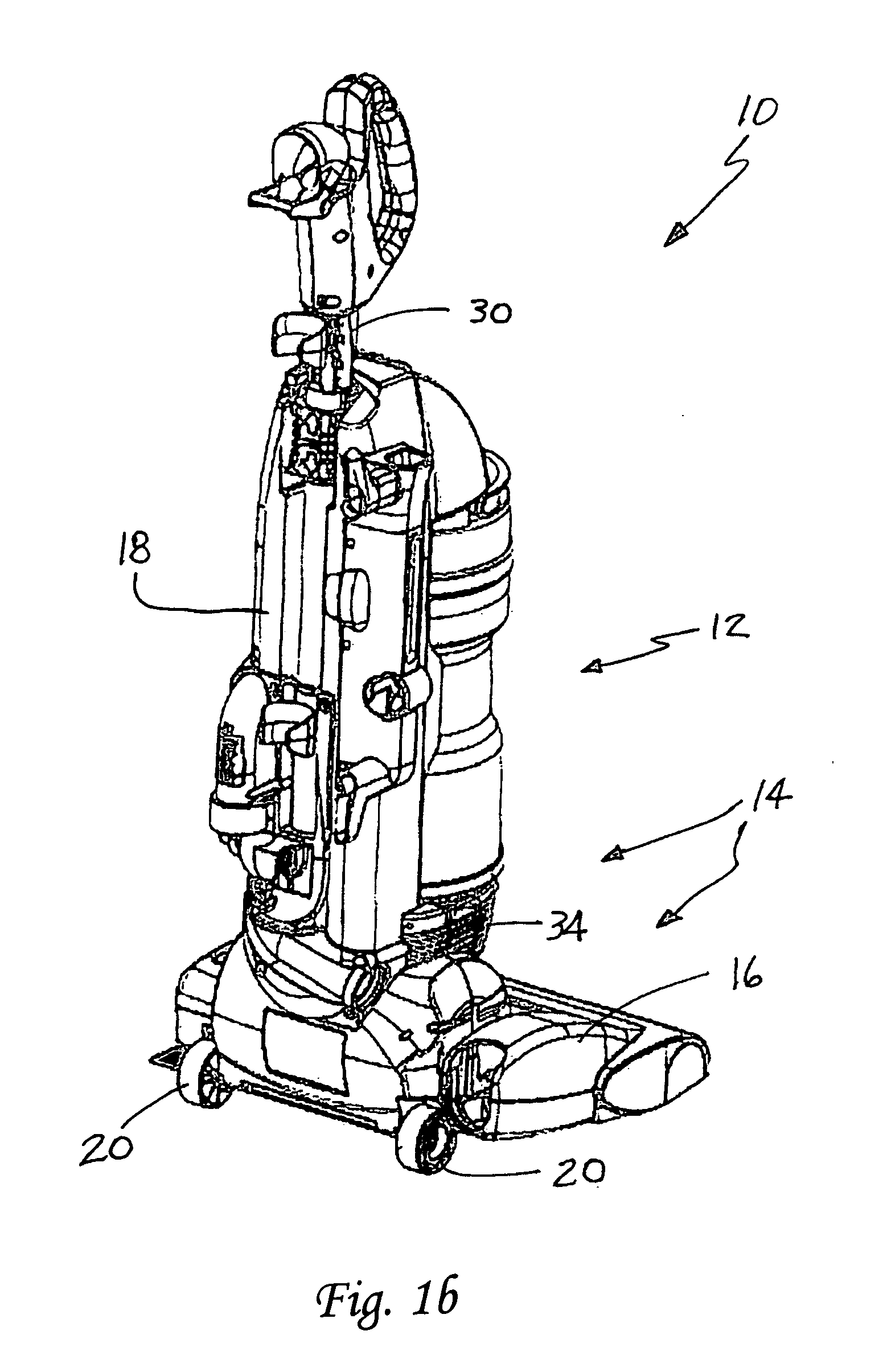
[0020]The vacuum cleaner 10 includes a body, generally designated by reference numeral 14. The body 14 includes a nozzle assembly 16 and a control or handle assembly 18. As is known in the art, the control assembly 18 is pivotally connected to the nozzle assembly 16 to aid the operator in manipulating the vacuum cleaner 10 back and forth across the floor. Wheels 20 (only two illustrated) carried on the body 14 allow the vacuum cleaner 10 to be moved smoothly across the floor. As illustrated, the nozzle assembly 16 is equipped with a suction inlet 22. A rot...


PUM


Abstract

A vacuum cleaner includes a body having a nozzle assembly including a suction inlet and a control assembly. A suction generator and a dirt collection vessel are both carried on the body. The dirt collection vessel includes a fine particle separator unit having at least one sling shot separator. Each sling shot separator includes a flow channel having an inlet, a debris discharge port and a clean air discharge port. The flow channel has a radius of curvature of between about 12 mm and about 25 mm and extends in an arc of less than 360° from the inlet to the clean air discharge outlet.

Description

TECHNICAL FIELD AND INDUSTRIAL APPLICABILITY OF THE INVENTION [0001]The present invention relates generally to the floor care equipment field and, more particularly, to a highly efficient and effective vacuum cleaner incorporating a fine particle separator unit having at least one sling shot separator.BACKGROUND OF THE INVENTION [0002]Cyclonic vacuum cleaners have long been known in the art. Such vacuum cleaners remove dirt and debris from the air stream by means of vortex separation. Specifically, a high speed rotating air flow is established within a cylindrical chamber often referred to as a cyclone. Air flows in a spiral pattern before exiting the cyclone through an axially directed outlet. Rotational effects, centrifugal force and gravity all function to separate dirt and debris from the air stream. Specifically, larger particles in the rotating stream have too much inertia to follow the tight curve of the stream. Such particles strike the outer wall of the cyclone falling to t...

Claims


Application Information

Patent Timeline
Patent Type & Authority Applications(United States)
IPC IPC(8): A47L9/00
CPCA47L9/1608A47L9/1641A47L9/1625
Inventor PROFFITT, II, DONALD E.STRECIWILK, ERIC J.FRY, MICHAEL L.
Owner PANASONIC OF NORTH AMERICA
Why Eureka
Try Eureka