Cooling device and method with synthetic jet actuator

a technology of cooling device and actuator, which is applied in the direction of indirect heat exchanger, lighting and heating apparatus, and semiconductor/solid-state device details, etc., can solve the problems of increasing the size of heat sink and ancillary components, such as pumps or circulation hardware, and the scale-up

Active Publication Date: 2011-02-03
AEROJET ROCKETDYNE OF DE
View PDF20 Cites 26 Cited by
  • Summary
  • Abstract
  • Description
  • Claims
  • Application Information

AI Technical Summary

Problems solved by technology

However, the scale-up increases the size of the heat sink ...

Method used


Image

  • Cooling device and method with synthetic jet actuator
  • Cooling device and method with synthetic jet actuator
  • Cooling device and method with synthetic jet actuator

Examples


Embodiment Construction

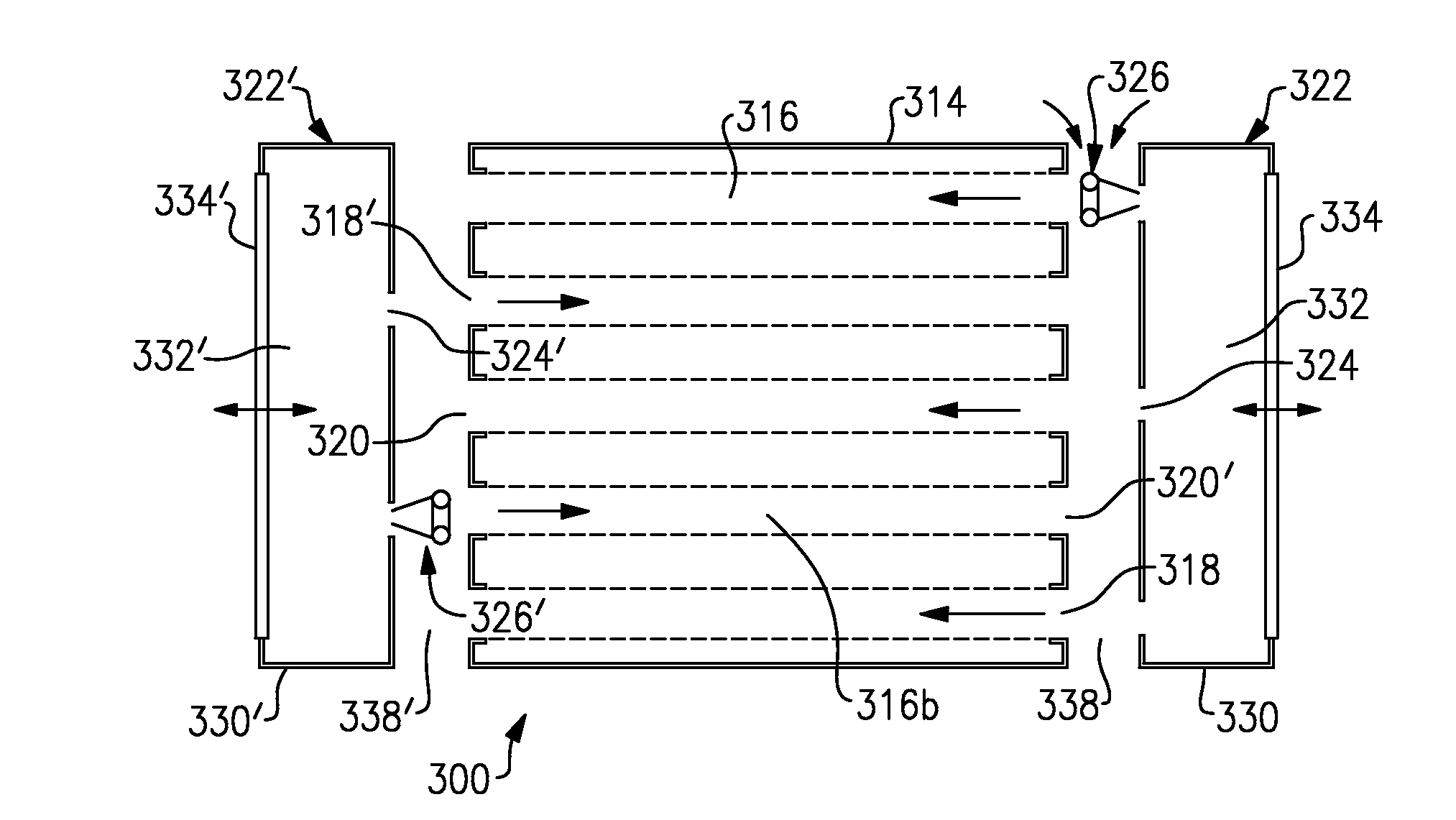
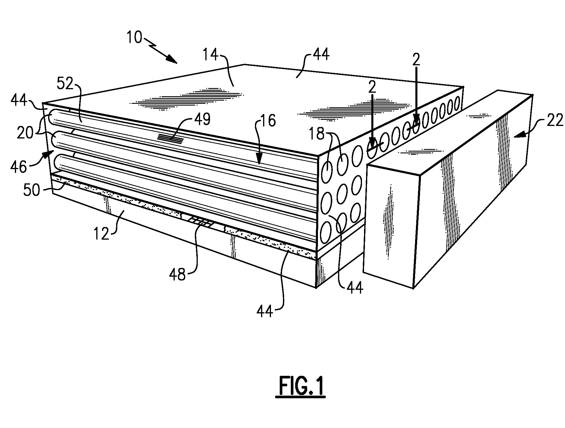
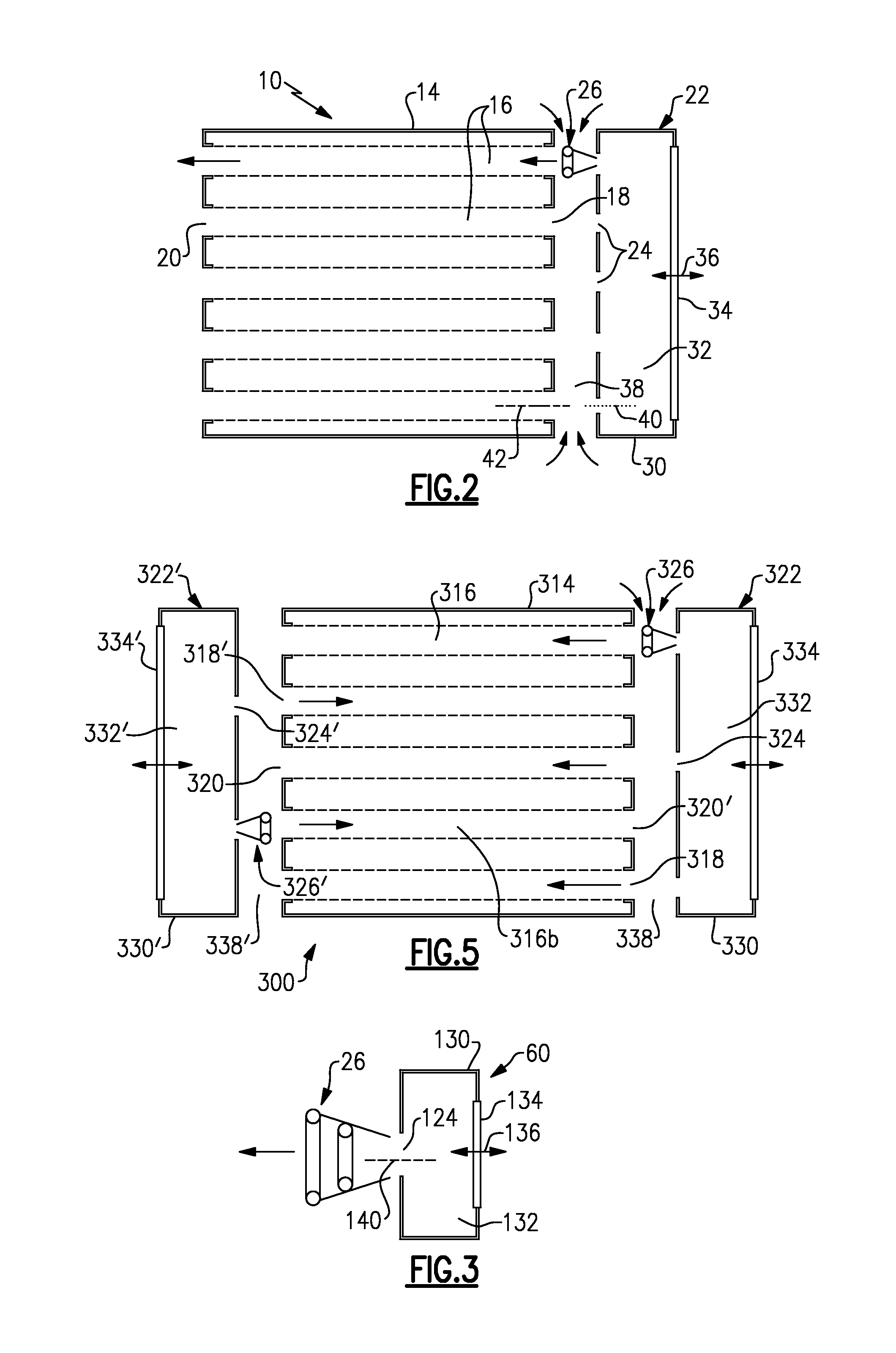
[0014]FIG. 1 illustrates a perspective view of selected portions of an example cooling device 10, and FIG. 2 illustrates a sectional view of a portion of the cooling device 10. In this example, the cooling device 10 is mounted on an electronic device 12, such as a microchip, to function as a heat sink for distribution and removal of heat produced by the electronic device 12. As may be appreciated, the cooling device 10 may be used with other types of heat producing bodies and is not limited to use in electronics. Additionally, although the cooling device 10 may be relatively small to match the size of the electronic device 12, the cooling device 10 is scalable to larger or smaller sizes to accommodate other types of heat producing bodies.

[0015]In the illustrated example, the cooling device 10 includes a heat sink body 14 having a plurality of elongated channels 16 that extend between respective channel inlets 18 and channel outlets 20. In this case, each of the channels 16 extends l...


PUM


Abstract

A cooling device includes a heat sink body having a plurality of elongated channels that extend between respective channel inlets and outlets. A synthetic jet actuator module is adjacent to the heat sink body and includes a plurality of jet outlets adjacent to the respective channel inlets for emitting a plurality of vortices into the channels.

Description

BACKGROUND OF THE INVENTION[0001]This disclosure relates to cooling devices and, more particularly, to a cooling device that utilizes a synthetic jet actuator to reduce cooling device size and increase cooling efficiency.[0002]Heat producing devices, such as electronic devices, generate waste heat that must be removed to maintain the device at a suitable operating temperature. For instance, electronic devices may utilize a heat sink, such as a solid medium, heat pipes, pumped loops, or the like to distribute the heat from the device to a larger area that dissipates the heat to the ambient surroundings.[0003]The power density of electronic devices is increasing due to greater junction densities, and the amount of heat that the device produces is likewise increasing. Typical heat sinks may be scaled-up to provide greater heat-removal capacity. However, the scale-up increases the size of the heat sink and ancillary components, such as pumps or circulation hardware.SUMMARY OF THE INVENT...

Claims


Application Information

Patent Timeline
IPC IPC(8): F28D15/00F28F7/00
CPCF28D1/05333F28D7/16F28D15/0233F28D2021/0029F28F9/0231F28F9/026H01L2924/0002F28F13/08F28F13/10H01L23/467H01L2924/00F28F13/187
Inventor GERLACH, DAVID W.
Owner AEROJET ROCKETDYNE OF DE
Why Eureka
Try Eureka