Optical flue gas monitor and control

a flue gas monitor and optical technology, applied in the direction of emission prevention, combustion types, instruments, etc., can solve the problems of system, especially mechanical systems, taking a long time to react, and the accuracy of sensors tends to be inaccurate, so as to achieve the effect of reducing the concentration

Inactive Publication Date: 2011-02-24
ALSTOM TECH LTD
View PDF22 Cites 33 Cited by
  • Summary
  • Abstract
  • Description
  • Claims
  • Application Information

AI Technical Summary

Benefits of technology

[0018]The system includes at least one monitoring device 220 having a number of optical sources 221 with each optical source 221 passing an optical beam through the flue gasses to a corresponding detector 222. Each detector 222 creates a number of sensed signals, the sensed signals are combined to provide a signal indicating the concentration of a constituent in the flue gasses. The monitoring system sends the combined signal to the control unit 230 to control furnace 1 to minimize the concentration of the constituent emitted in the flue gasses.

Problems solved by technology

These sensors tend to be inaccurate since they only measure O2 at a specific sensor location.
Some systems, especially mechanical systems, take some time to react.

Method used


Image

  • Optical flue gas monitor and control
  • Optical flue gas monitor and control
  • Optical flue gas monitor and control

Examples


Embodiment Construction

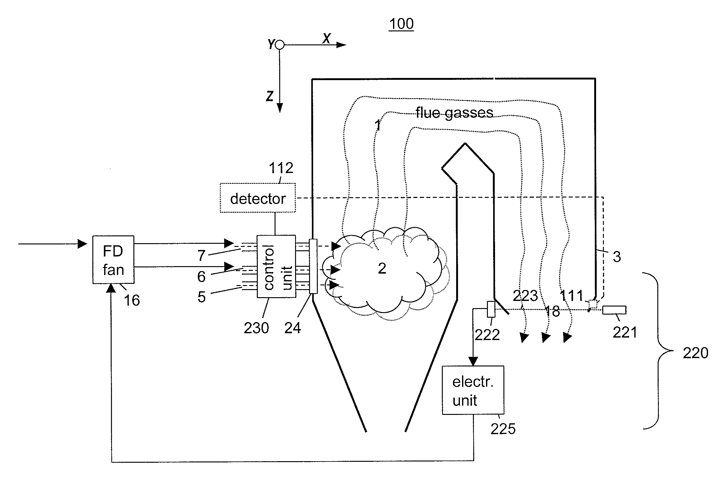
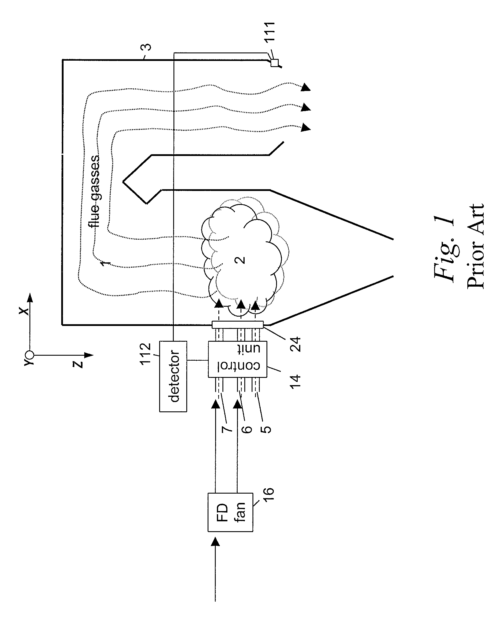
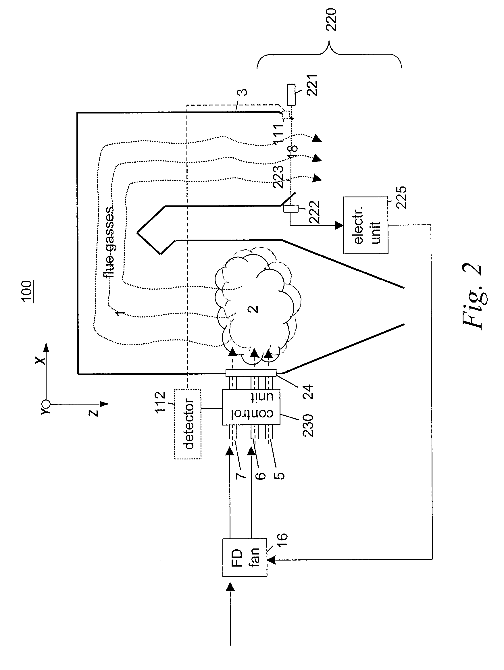
[0026]Disclosed is a method and apparatus for providing for accurate monitoring of combustion conditions, flue gas constituents from a combustion system, and controlling the combustion system and / or emission control devices based upon the monitoring. In various non-limiting embodiments provided herein, the combustion system is a solid fuel, gaseous or liquid fuel fired combustion system. The combustion system may be a combination furnace and boiler, or steam generator. One skilled in the art will recognize, however, that the embodiments provided are merely illustrative and are not limiting of the invention.

[0027]The methods and apparatus make use of optical detection systems. As provided herein, the optical signaling and detection systems are simply referred to as a “monitoring system.” In general, the monitoring system includes a variety of components for performing a variety of associated functions. The components may include a plurality of optical sources such as lasers, a plural...


PUM

PropertyMeasurementUnit
densityaaaaaaaaaa
concentrationaaaaaaaaaa
opticalaaaaaaaaaa

Abstract

A plurality of optical monitoring systems 220,320 sense the concentration of at least one constituent in flue gasses of a furnace 1 and its emission control devices. The monitoring devices 220,320 includes at least one optical source 221 for providing beams 223 through a sampling zone 18 to create a combined signal indicating the amount of various constituents within the sampling zone 18. The combined signal may be fed forward to emission control devices to prepare them for oncoming emissions. The combined signals may also feed backward to adjust the emission control devices. They may also be provided to a control unit 230 to control stoicheometry of the burners of furnace 1. This results in a more efficient system that reduces the amount of emissions released.

Description

CROSS REFERENCE TO RELATED APPLICATIONS[0001]This application is related to co-pending U.S. patent application entitled “BURNER MONITOR AND CONTROL” by the same inventor, Michael Tanca, filed on the same day as the present application. This applications incorporates the above-referenced application as if it were set forth in its entirety herein.BACKGROUND OF THE INVENTION[0002]1. Field of the Invention[0003]This invention relates to coal-fired combustion systems, and more particularly to a flue gas monitoring system for accurate control of emissions of coal-fired combustion systems.[0004]2. Description of the Related Art[0005]In various coal-fired combustion systems, combustion is monitored by a measurement device located in the rear of the furnace. Typically, this is an oxygen sensor. This measurement device provides feedback signals that are used to control the combustion within the combustion system. These sensors tend to be inaccurate since they only measure O2 at a specific sen...

Claims


Application Information

Patent Timeline
Patent Type & Authority Applications(United States)
IPC IPC(8): F23N1/02F23N5/00F23J15/02G01N21/00
CPCF23D1/02F23J15/003F23J15/022F23J15/04F23J2215/00F23N2900/05003F23J2219/00F23N5/003F23N5/08F23N5/082F23N2900/05002F23J2217/00F23J15/00F23J15/02F23N5/00
Inventor TANCA, MICHAEL C.
Owner ALSTOM TECH LTD
Why Eureka
Try Eureka