Production method of an electroacoustic transducer diaphragm, electroacoustic transducer diaphragm, and an electroacoustic transducer
a production method and technology of electroacoustic transducers, applied in the direction of transducer diaphragms, instruments, manufacturing tools, etc., can solve the problems of insufficient smoothness and stretchability of wooden sheets in hot press molding, damage to wooden sheets still in molds, and easy damage of diaphragms, etc., to achieve convenient production, provide practical strength, and absorb more moisture
- Summary
- Abstract
- Description
- Claims
- Application Information
AI Technical Summary
Benefits of technology
Problems solved by technology
Method used
Image
Examples
first embodiment
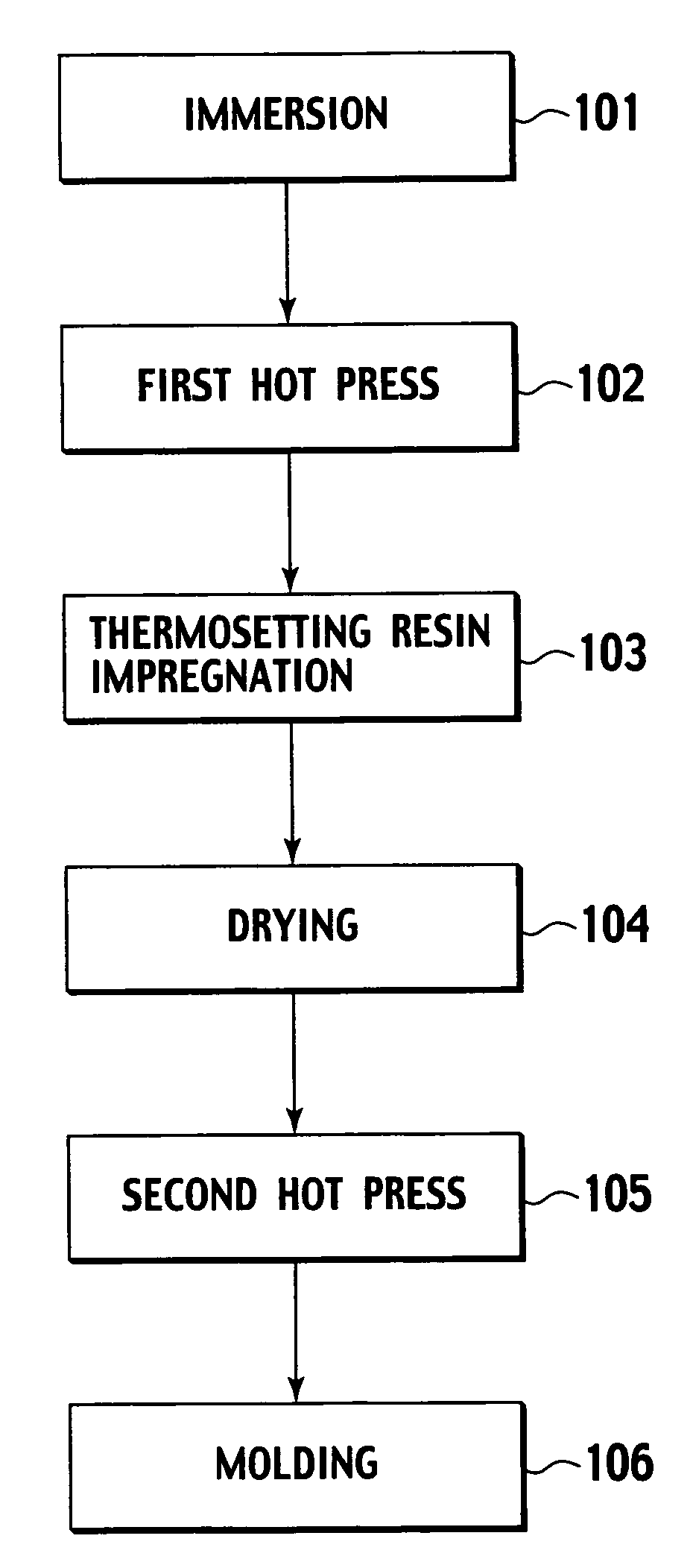
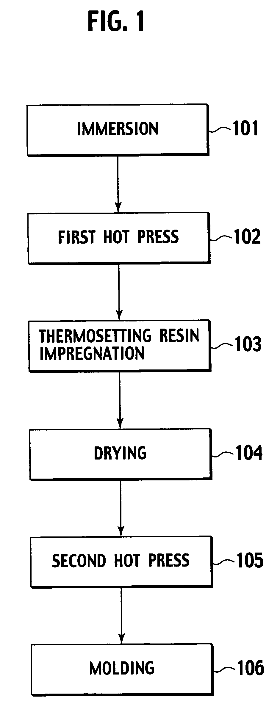
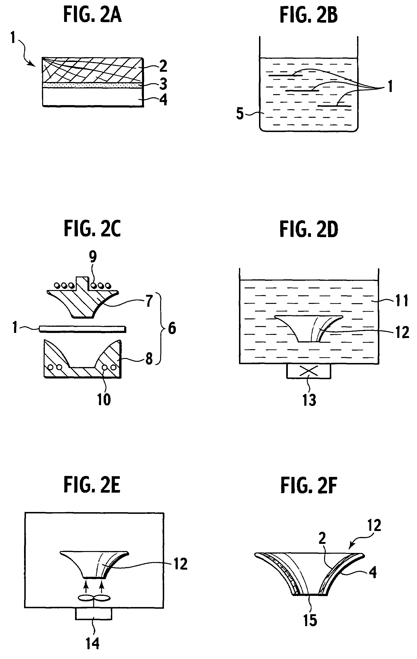
[0038]A first embodiment of the present invention will be described below. FIG. 1 is a flow chart showing a production method of an electroacoustic transducer diaphragm according to the present invention. FIG. 2 is an explanatory diagram of the production method according to the first embodiment.
[0039]Firstly, in a immersing step 101 in FIG. 1, as shown in FIG. 2A, an adhered sheet 1 is produced by adhering a non-woven cloth 4 on one surface of a wooden sheet 2 having a thickness of approximately 0.25 mm via an adhesive layer 3 therebetween. The adhered sheet 1 is cut into a preferred size. As shown in FIG. 2B, the adhered sheet 1 is immersed in a solution 5 which contains 0.05 wt % of sodium butylnaphthalene sulfonate. The adhered sheet 1 is kept immersed until it becomes flexible (approximately 20 minutes).
[0040]In a first hot press molding step 102 in FIG. 1, as shown in FIG. 2C, the flexible adhered sheet 1 is hot press molded by a mold 6 which is heated to temperatures of 100° ...
second embodiment
[0048]A second embodiment of the present invention will be explained below with reference to FIGS. 1 and 3A to 3F.
[0049]Firstly, in a immersing step 101 in FIG. 1, as shown in FIG. 3A, an adhered sheet 16 is produced by adhering a sheet of Japanese paper 19 on one surface of a wooden sheet 17 having a thickness of approximately 0.25 mm via an adhesive layer 18 therebetween. As shown in FIG. 3B, the adhered sheet 16 is cut into a preferred size and immersed in a solution 20 which contains 5 wt % of ethylene glycol and 0.1 wt % of sodium di(-2-ethylhexyl) sulfosuccinate. The adhered sheet 16 is kept immersed until it becomes flexible (approximately 20 minutes). Here, small amount of ethyl alcohol is dissolved in the solution 20 to reduce the time of drying the workpiece.
[0050]In a first hot press molding step 102 in FIG. 1, as shown in FIG. 3C, the flexible adhered sheet 16 is hot press molded by a mold 21 which is heated to temperatures of 100° C. or more in advance. The mold 21 is o...
third embodiment
[0056]A third embodiment of the present invention will be described below with reference to FIGS. 1 and 4A to 4F.
[0057]Firstly, in a immersing step 101 in FIG. 1, as shown in FIG. 4A, an adhered sheet 28 is produced by adhering a non-woven cloth 31 on one surface of a wooden sheet 29 having a thickness of approximately 0.5 mm via an adhesive layer 30 therebetween. As shown in FIG. 4B, the adhered sheet 28 is cut into preferred size and immersed in a solution 32 which contains 0.1 wt % of sodium di(-2-ethylhexyl) sulfosuccinate. The adhered sheet 28 is kept immersed until it becomes flexible (approximately 20 minutes).
[0058]In a first hot press molding step 102 in FIG. 1, as shown in FIG. 4C, the flexible adhered sheet 28 is hot press molded by a mold 33 which is heated to temperatures of 100° C. or more in advance. The mold 33 is a mold of a male-female type which is composed of a male mold 34 and a female mold 35 and includes heaters 36, 37. Since the solution 32 does not contain a...
PUM
| Property | Measurement | Unit |
|---|---|---|
| thickness | aaaaa | aaaaa |
| wt % | aaaaa | aaaaa |
| wt % | aaaaa | aaaaa |
Abstract
Description
Claims
Application Information
 - R&D
- Intellectual Property
- Life Sciences
- Materials
- Tech Scout
- Unparalleled Data Quality
- Higher Quality Content
- 60% Fewer Hallucinations
Browse by: Latest US Patents, China's latest patents, Technical Efficacy Thesaurus, Application Domain, Technology Topic, Popular Technical Reports.
© 2025 PatSnap. All rights reserved.Legal|Privacy policy|Modern Slavery Act Transparency Statement|Sitemap|About US| Contact US: help@patsnap.com


