

Coil apparatus
- Summary
- Abstract
- Description
- Claims
- Application Information
AI Technical Summary
Benefits of technology
Problems solved by technology
Method used
Image

Examples
first embodiment
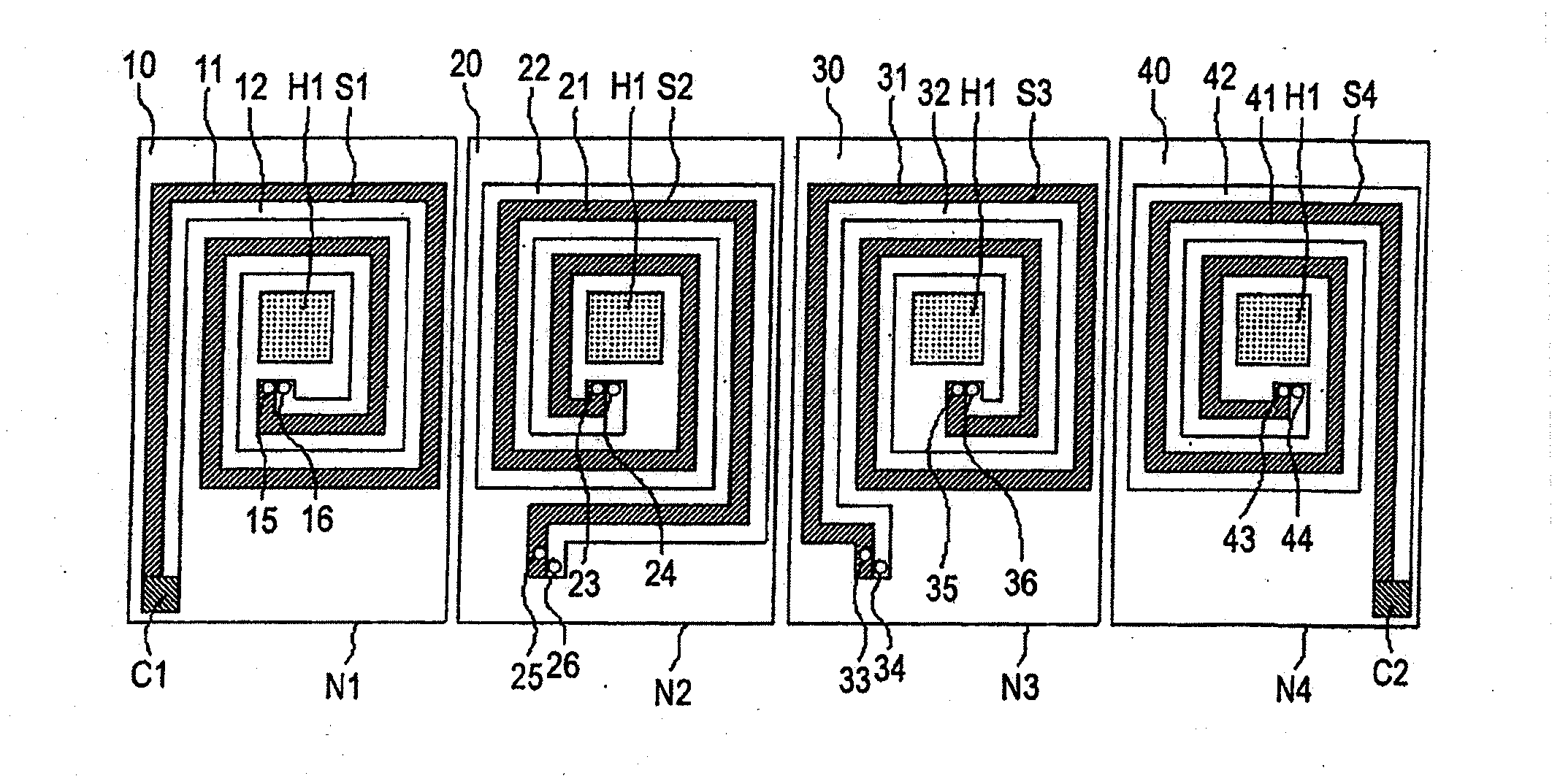
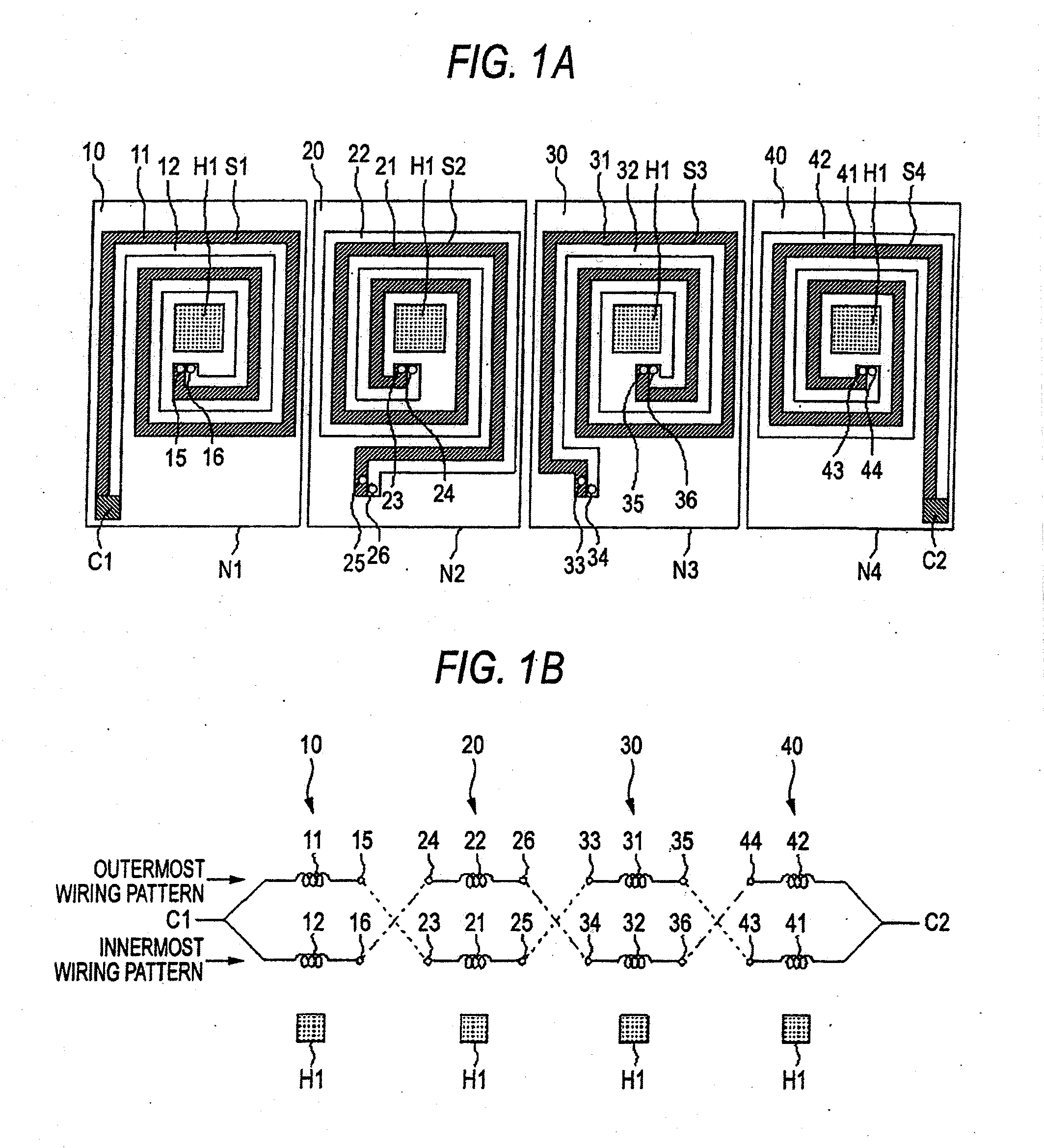
[0015]FIG. 1A is a view showing an array configuration of a wiring pattern formed in each wiring layers in a coil apparatus of a first embodiment, and FIG. 1B is a view showing an connection configuration of a wiring pattern formed in each wiring layers in a coil apparatus of the first embodiment. As shown in FIGS. 1A and 1B, the coil apparatus of the first embodiment is configured so that: a coil pattern is formed into spiral shape around a core-insertion hole H1 for inserting a core, on each wiring layers N1 to N4 including a first wiring layer N1, a second wiring layer N2, a third wiring layer N3 and a fourth wiring layer N4; the each wiring layer N1 to N4 are laminated in the order of N1 (an uppermost wiring layer), N2, N3, N4 (a lowest wiring layer) as enumerated from the topside; the coil patterns formed on each wiring layers N1 to N4 are serially connected through a via-hole (which is called as a conduction hole to electrically connect the wiring layers each other); the coil ...
second embodiment
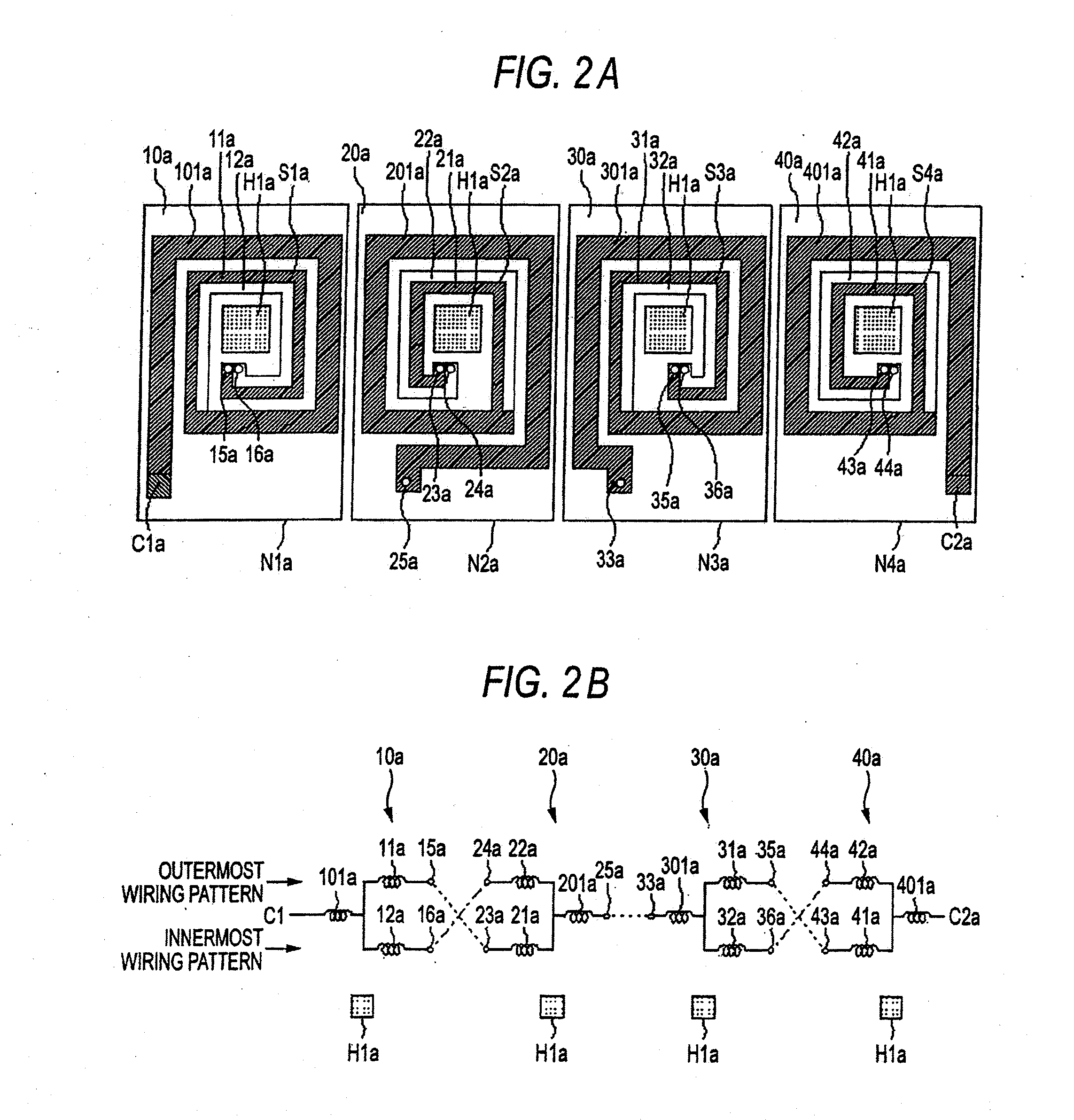
[0026]FIG. 2A is a view showing an array configuration of a wiring pattern formed in each wiring layers in a coil apparatus of a second embodiment, and FIG. 2B is a view showing an connection configuration of a wiring pattern formed in each wiring layers in a coil apparatus of the second embodiment. FIGS. 2A and 2B are different from the configuration of the first embodiment shown in FIGS. 1A and 1B. In the FIGS. 1A and 1B, the slit is provided along a current direction in the whole of the coil pattern from one end to another end, on the other hand, in case of the second embodiment, a slit is provided along a current direction in a part of a coil pattern in a region near a core-insertion hole (a region susceptible to leakage flux that leaks from a core).
[0027]At a spiraled wiring portion near a core-insertion hole H1a, a coil pattern 10a formed on a first wiring layer N1a is divided into an outermost wiring pattern 11a and an innermost wiring pattern 12a, which have the same widths,...
third embodiment
[0037]In the first embodiment, the coil pattern formed on the respective wiring layers is divided into a plurality of sub-coil patterns. As a result, as the number of the wiring layers (the number of stacked layers) increases, the number of the via-holes also increases. When the number of the via-holes increases, a region where the wiring patterns can be formed may be reduced, so that the wiring length of the wiring pattern may become longer.
[0038]According to a third embodiment, a coil pattern in a surface-side wiring layer that is susceptible to leakage flux that leaks from a core is divided into a plurality of wiring patterns. A coil pattern in an intermediate wiring layer that is not susceptible to leakage flux that leaks from a core is not divided into sub-wiring patterns and is provided as one wiring pattern (single coil pattern).
[0039]FIG. 3A is a view showing an array configuration of a wiring pattern formed in each wiring layers in a coil apparatus of a third embodiment, an...
PUM
 Abstract
Description
Claims
Application Information