Draw latch with safety catch

a technology of draw latches and safety catch, which is applied in the direction of carpet fasteners, keyhole guards, mechanical devices, etc., can solve the problems of easy bending of the exposed spring element of the safety locking arrangement, the inability to reliably use the hook type catch in heavy duty, and the positive control of the safety latch

Inactive Publication Date: 2011-03-24
KOPYLOV EDUARD
View PDF26 Cites 11 Cited by
  • Summary
  • Abstract
  • Description
  • Claims
  • Application Information

AI Technical Summary

Problems solved by technology

The Catch with Antirelease Latch by Gunnar E. Swanson in U.S. Pat. No. 3,602,723 Proposes hook type safety catch which engagement concealed within device, such arrangement does not offer positive control of the safety latch engagement and hook type catch is not reliable in heavy duty applications
The exposed spring element of this safety locking arrangement is prone to bending in heavy duty application.
The Toggle Latch with Spring Catch presented by Conrad Gunther in U.S. Pat. No. 4,352,513 comprises spring type safety catch which is prone to bending and does not offer observable engagement.
The Handle Operated Draw Latch with Safety Catch disclosed by Weinerman et al U.S. Pat. No. 5,445,422 comprises hook type safety catch with too many complicated parts increasing cost of manufacturing and reducing reliability of performance.
The Over-center Latch disclosed by Norman Evans in U.S. Pat. No. 6,840,551 comprises safety catch which is pivotally movable in and out of engaged Position offers observable engagement, however, it requires significant angular rotation and rotating Catch Member is a cantilever extending from the pivotal point and is prone to bend and jam.

Method used


Image

  • Draw latch with safety catch
  • Draw latch with safety catch
  • Draw latch with safety catch

Examples


Embodiment Construction

[0051]Although specific features of the invention are shown in some drawings and not others, this is for convenience only as each feature may be combined with any or all of other features in accordance with the invention.

[0052]While preferred illustrative embodiments of the invention are described above, it will be apparent to those skilled in the art that various changes and modifications may be made without departing from the invention.

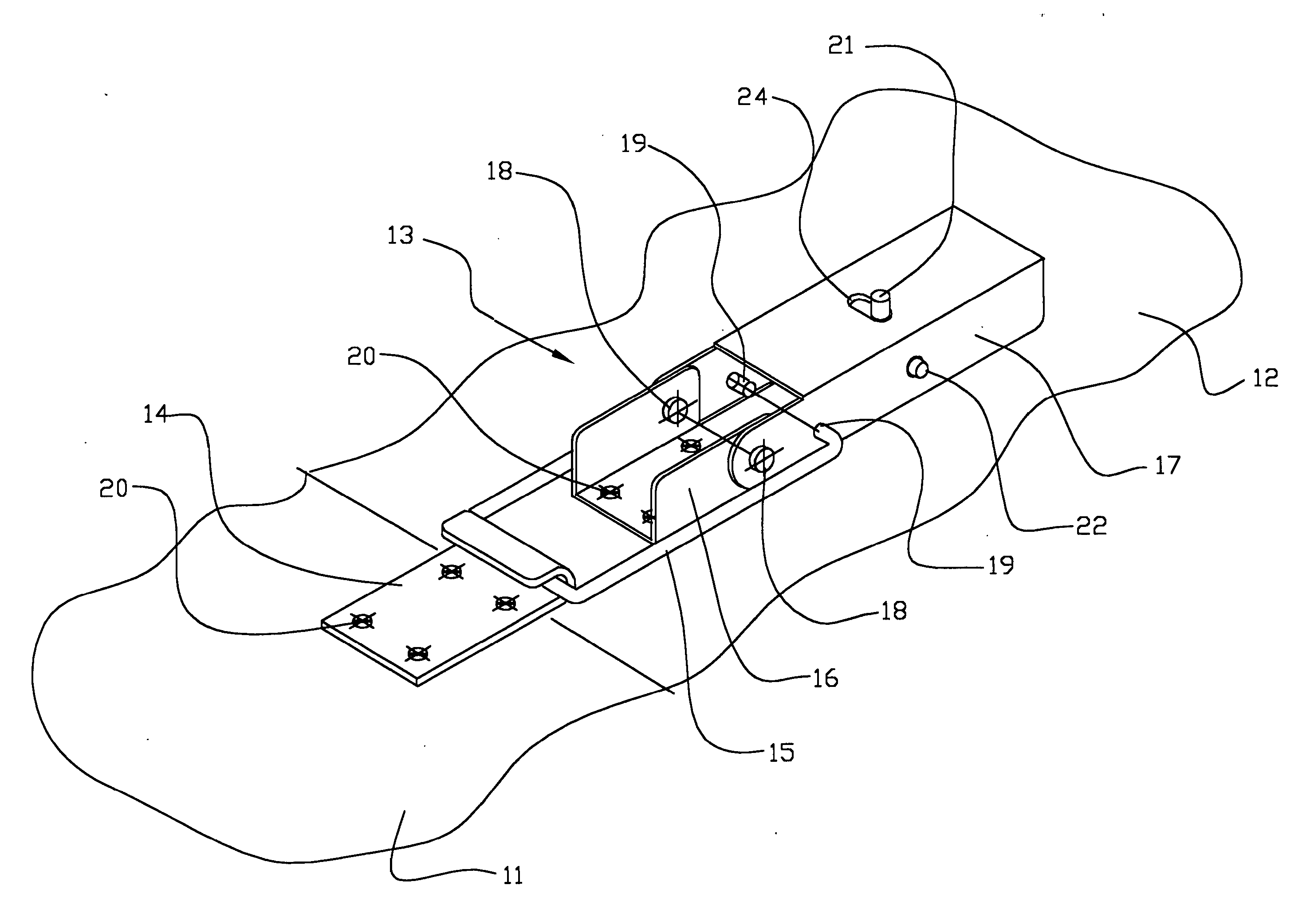
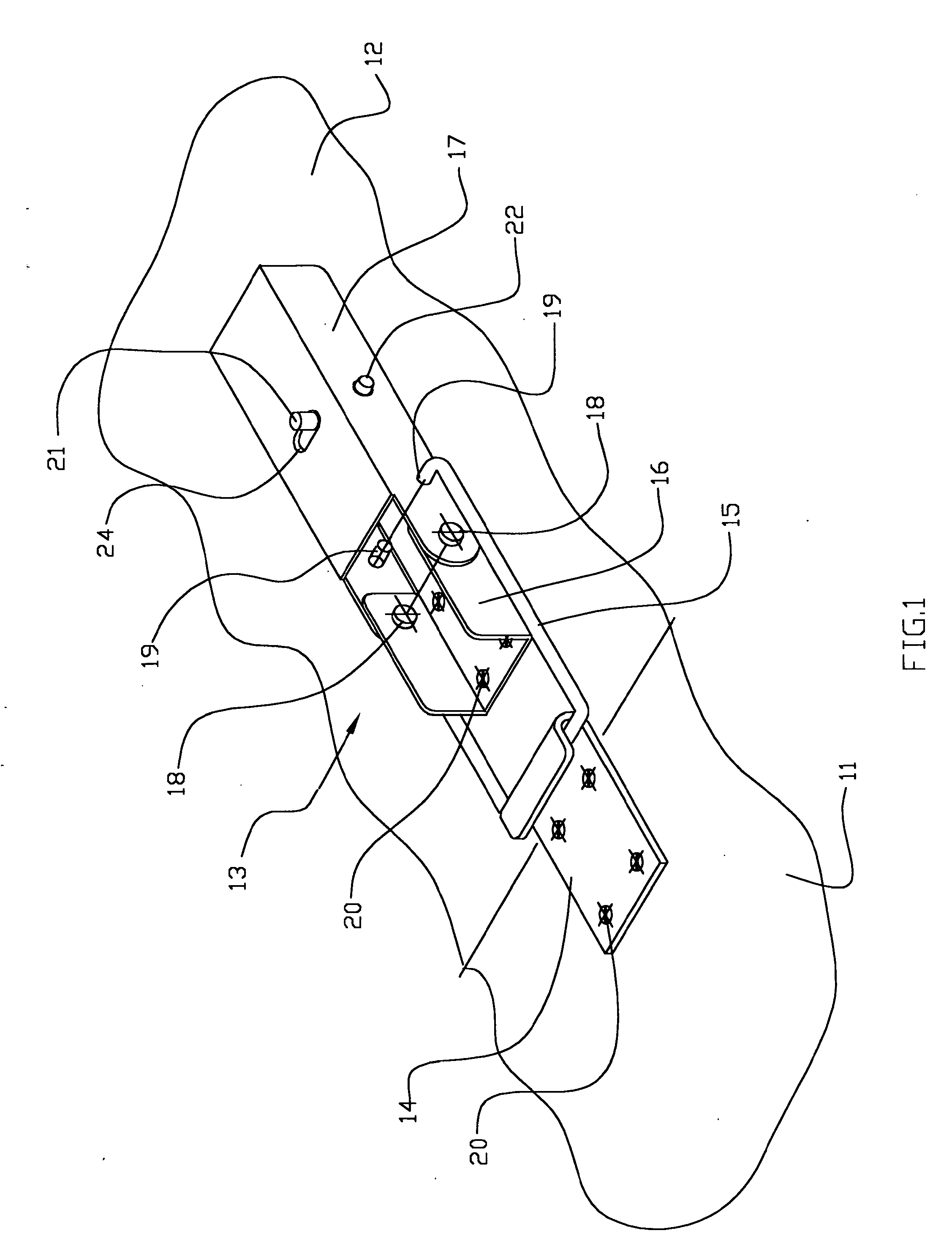
[0053]The appended claims are intended to cover all changes within the spirit of the invention. A preferred embodiment of the inventive draw latch is illustrated in FIGS. 1-5.

[0054]Referring now to FIG. 1, which is an isometric view of the inventive draw latch 13 fastening together two members 11 and 12. The latch is shown in closed position where the loop style draw bar 15 pulling the hook style edge of the draw plate 14 coupled to the member 11 and the base 16 of the latch is coupled to the member 12 by fasteners 20. Additionally, the latch compri...


PUM


Abstract

A draw latch 13 with a safety catch for fastening two members 11 and 12, where said latch comprises a base 16 attached to said member 12, a lever 17 pivotally connected to said base 16 for movement between closed and open positions, a draw bar 15 pivotally connected with one end to said lever 17 providing toggle action upon the latch lever 17 closing and another end of said draw bar 15 is for engagement with a draw plate 14 attached to said member 11. Said safety catch comprises a safety catch bolt 22 with thumb knob 21, where said bolt 21 is supported by a side wall of said lever 17 a support bracket 25 attached to said lever 17, said safety catch bolt 22 orientation is substantially parallel to the pivotal axis of said latch lever 17. A compression spring 26 being mounted on said safety catch bolt 22 forces said bolt into locked position to engage a latch base tab 23 and an engagement hole 28 on another wall of said latch lever 17 allowing said bold to protrude through this wall and preventing the latch to open. The safety catch can be open by pushing said knob 21 into the open position, so said safety catch bolt 22 will disengage allowing the lever 17 to be lifted to open the latch. Said latch draw bar can be designed to accommodate dimensional variations.

Description

CROSS-REFERENCE TO RELATED APPLICATIONS[0001]Not ApplicableFEDERALLY SPONSORED RESEARCH[0002]Not ApplicableSEQUENCE LISTING OF PROGRAM[0003]Not ApplicableBACKGROUND OF INVENTION[0004]1Field of Invention[0005]This invention relates generally to heavy duty, toggle type draw latches for connecting two relatively movable members.[0006]Some of such latches, existing on the market, are equipped with safety locking means which are such like provisions for padlock installation, hook type catches, locks requiring keys, spring hooks, rotational locking cams are either expensive to manufacturer or not reliable in heavy duty applications.[0007]The is need for a draw latch with simple, durable, reliable secondary catch with exposed engagement which will be able to operate reliably in heavy duty applications.[0008]2. Prior Art[0009]The Catch with Antirelease Latch by Gunnar E. Swanson in U.S. Pat. No. 3,602,723 Proposes hook type safety catch which engagement concealed within device, such arrange...

Claims


Application Information

Patent Timeline
Patent Type & Authority Applications(United States)
IPC IPC(8): E05C3/14
CPCE05C19/14E05B13/002Y10S292/49Y10T292/0871Y10T292/0917Y10T292/108
Inventor KOPYLOV, EDUARD
Owner KOPYLOV EDUARD
Why Eureka
Try Eureka