Internal baffling for fuel injector

a fuel injector and internal baffling technology, which is applied in the direction of burners, combustion types, combustion processes, etc., can solve the problems of high velocity past the first mixing tube seen by the gas, very low velocities at the outermost mixing tube, and substantial total pressure gradient within the nozzl

Active Publication Date: 2011-03-31
GENERAL ELECTRIC CO
View PDF18 Cites 40 Cited by
  • Summary
  • Abstract
  • Description
  • Claims
  • Application Information

AI Technical Summary

Problems solved by technology

However, when this is done without regard to the internal flows of the gasses, the result is a very high velocity past the first mixing tubes seen by the gas and very low velocities at the outermost mixing tubes.
This results in a substantial total pressure gradient within the nozzle, which is very undesirable for achieving a uniform amount of gas being injected into each mixing tube.
In addition to the unacceptable pressure field the resulting very low velocities at the points furthest away from the feed tube produce very low cooling effectiveness, which can result in high metal temperatures and thus low part life.

Method used


Image

  • Internal baffling for fuel injector
  • Internal baffling for fuel injector
  • Internal baffling for fuel injector

Examples


Embodiment Construction

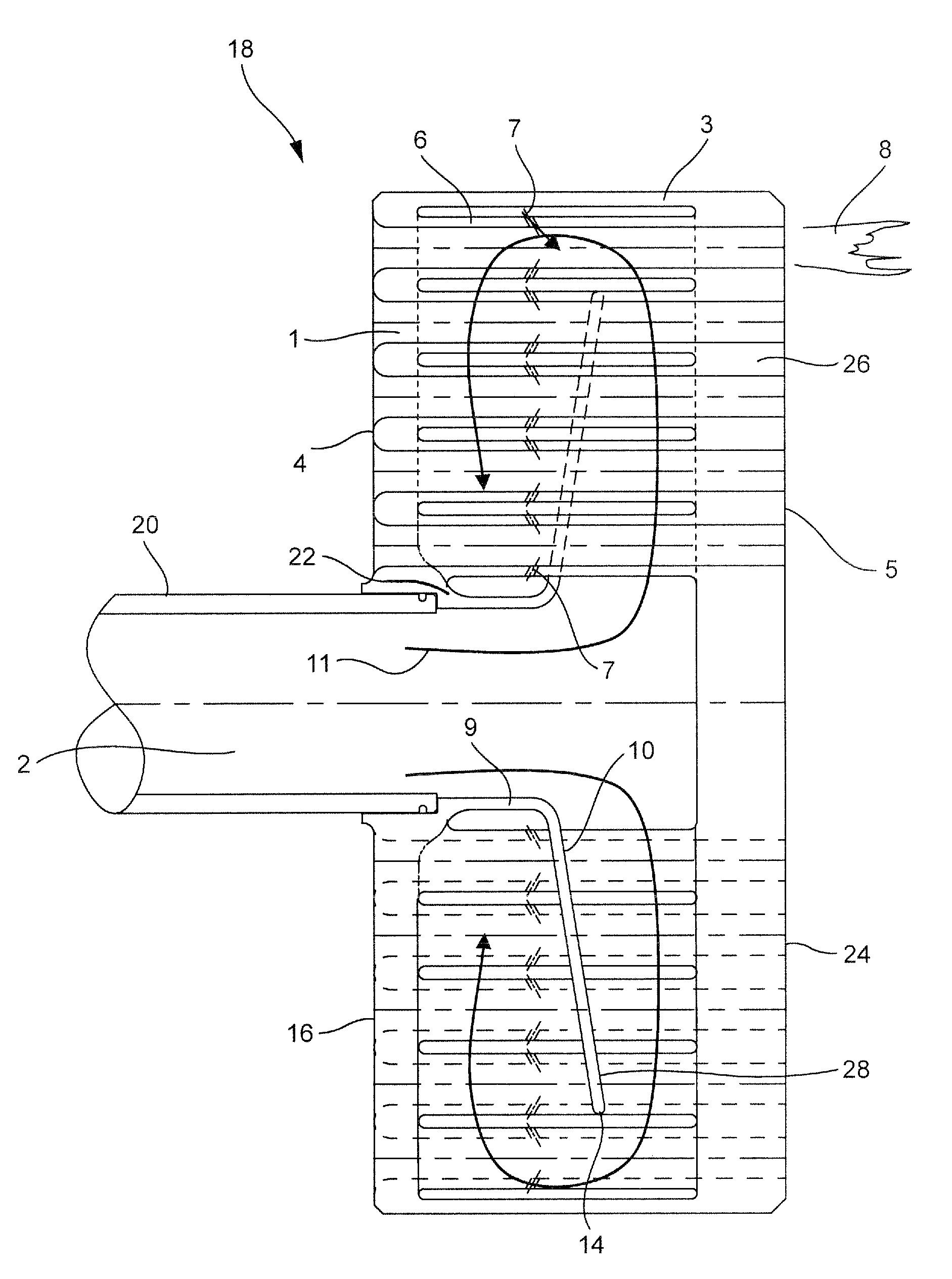
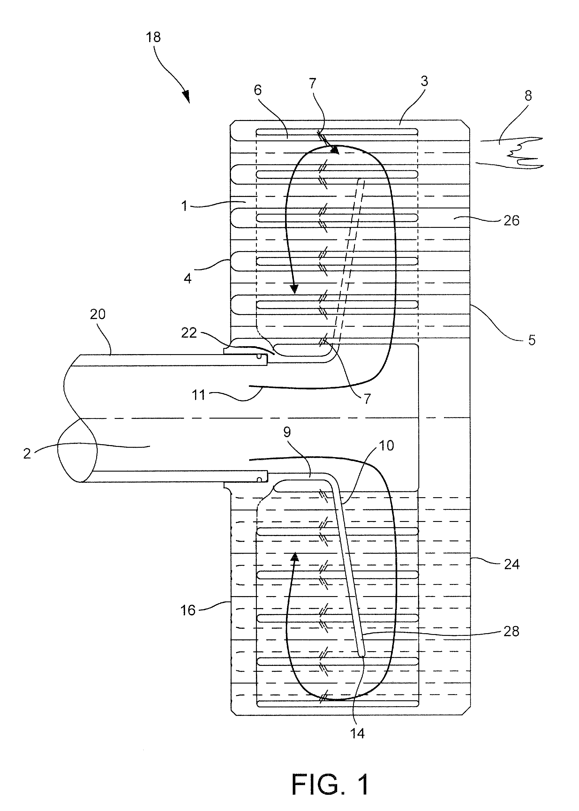
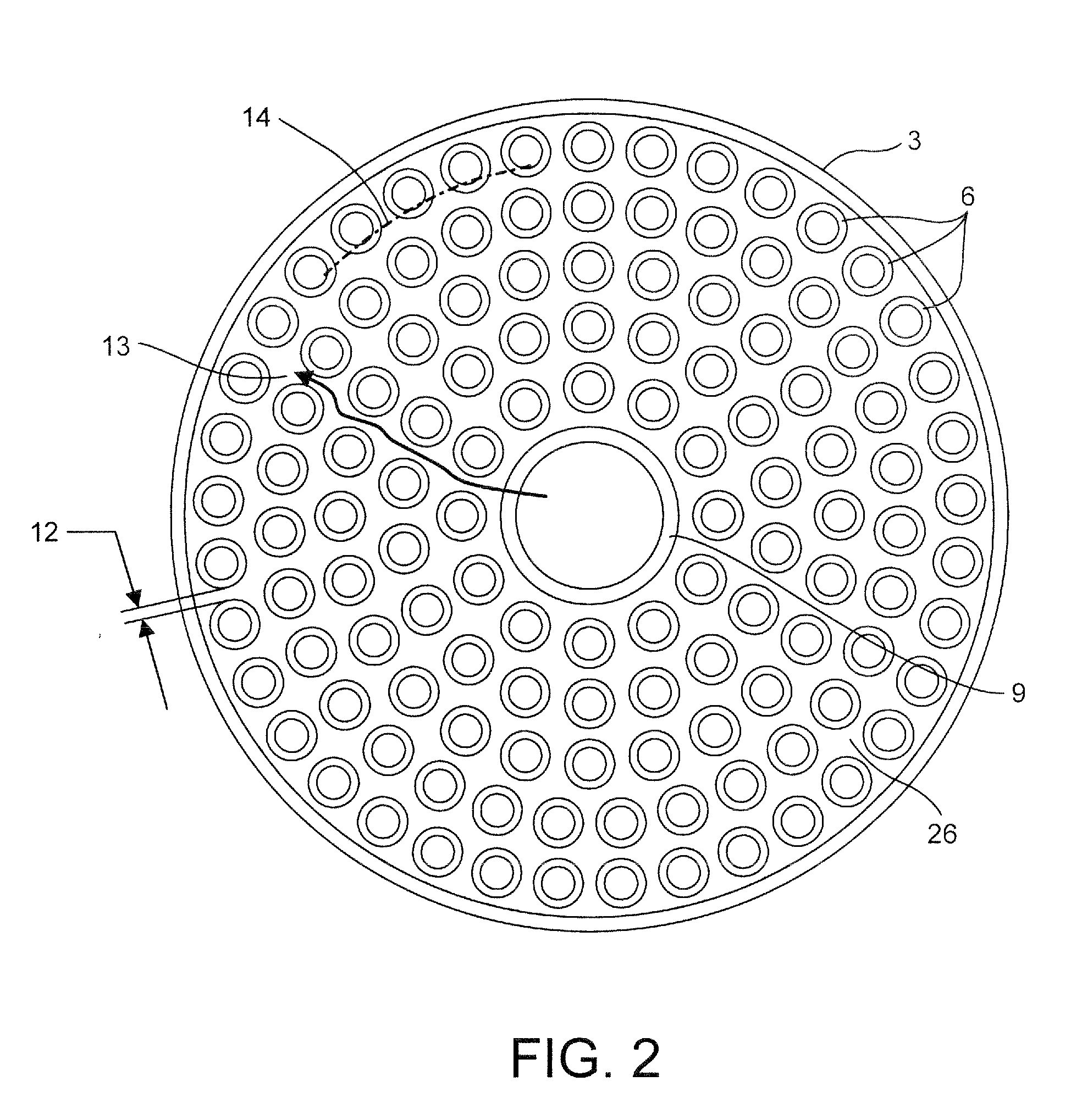
[0008]Referring to FIGS. 1 and 2, a fuel injector 18 comprises a fuel delivery tube 20 and a plurality of pre-mixing tubes 6. The pre-mixing tubes 6 are supported by a first, upstream tube support plate 16 at an upstream face or side 4 of the fuel injector and a second, downstream tube support plate 24 at a downstream face or side 5 of the fuel injector 18. An outer wall 3 connects the tube support plates 16, 24. A plenum 26 is formed by the outer wall 3 and the tube support plates 16, 24. The pre-mixing tubes 6 are supported by the first, upstream tube support plate 16 and the second, downstream tube support plate 24.

[0009]An internal baffle 22 is supported at the end of the fuel delivery tube 20. The internal baffle 22 includes a cylindrical portion 9 that is supported by the fuel delivery tube 20 and a radial portion 10 that extends radially into the plenum 26.

[0010]A fuel 2 enters the plenum 26 of the fuel injector 18 from the fuel delivery tube 20 connected to the first, upstre...


PUM


Abstract

A fuel injector includes a fuel delivery tube; a plurality of pre-mixing tubes, each pre-mixing tube comprising at least one fuel injection hole; an upstream tube support plate that supports upstream ends of the plurality of pre-mixing tubes; a downstream tube support plate that supports downstream ends of the plurality of pre-mixing tubes; an outer wall connecting the upstream tube support plate and the downstream tube support plate and defining a plenum therewith; and a baffle provided in the plenum. The baffle includes a radial portion. A fuel delivered in the upstream direction by the fuel delivery tube is directed radially outwardly in the plenum between the radial portion of the baffle and the downstream tube support plate, then in the downstream direction around an outer edge portion of the radial portion, and then radially inwardly between the radial portion and the upstream tube support plate.

Description

STATEMENT REGARDING FEDERALLY SPONSORED RESEARCH OR DEVELOPMENT[0001]This invention was made with Government support under Contract No. DE-FC26-05NT42643 awarded by the Department of Energy. The Government has certain rights in this invention.FIELD OF THE INVENTION[0002]The present invention relates to a fuel injector, and more particularly to a fuel injector including internal baffling.BACKGROUND OF THE INVENTION[0003]Fuel nozzles may be designed to pre-mix natural gas fuel. Fuel nozzles may also be designed to burn a hydrogen fuel which is much more reactive and hence has a much higher flame speed. The term pre-mixed combustion refers to fuel nozzles for combustion systems in which the air and fuel are introduced upstream of where the combustion process takes place. One approach to designing nozzles that burn high reactivity fuels is to do this premixing in very many small tubes for reasons such as increased quenching and to insure minimal recirculation zones behind the fuel jets....

Claims


Application Information

Patent Timeline
Patent Type & Authority Applications(United States)
IPC IPC(8): B05B1/14
CPCF23C2900/9901F23D14/02F23R3/286F23D2214/00F23D14/78
Inventor JOHNSON, THOMAS EDWARDLACY, BENJAMINSTEVENSON, CHRISTIAN
Owner GENERAL ELECTRIC CO
Why Eureka
Try Eureka