
Wind-water ultrasonic humidifier

a technology of ultrasonic humidifier and wind water, which is applied in the direction of lighting and heating equipment, heating types, color-music equipment, etc., can solve the problems of lack of artistic decorative appearance, expansion function, and high consumption of electric power, and achieves simple and fashioned decoration

Inactive Publication Date: 2011-03-31
CHEN HUI CHIN
View PDF14 Cites 3 Cited by
  • Summary
  • Abstract
  • Description
  • Claims
  • Application Information

AI Technical Summary

Benefits of technology

[0005]Therefore, it is a primary objective of the present invention to overcome the aforementioned shortcoming and deficiency of the prior art by providing a wind-water ultrasonic humidifier designed with a wonderful concept and a bold innovation, and adopting a ceramic housing with simple, and fashioned decoration instead of the traditional dull and boring housing. As to the structure and functions of the wind-water ultrasonic humidifier, wonderful structure and circuit control are used for simulating a natural raindrop effect, and various different rain falling scenes can be adjusted according to users' personal need or preference to achieve a unique natural wind-water state of mind, and a water circulation system is used for achieving the effect of driving a fan by waterflow.

Problems solved by technology

Present existing ultrasonic humidifiers generally require a fan to blow mists after water dripping and nebulization processes take place, and thus consume much electric power.
Furthermore, the conventional ultrasonic humidifiers lack of artistic decorative appearance, expansion function, and fun.

Method used


Image

  • Wind-water ultrasonic humidifier
  • Wind-water ultrasonic humidifier
  • Wind-water ultrasonic humidifier

Examples


Embodiment Construction

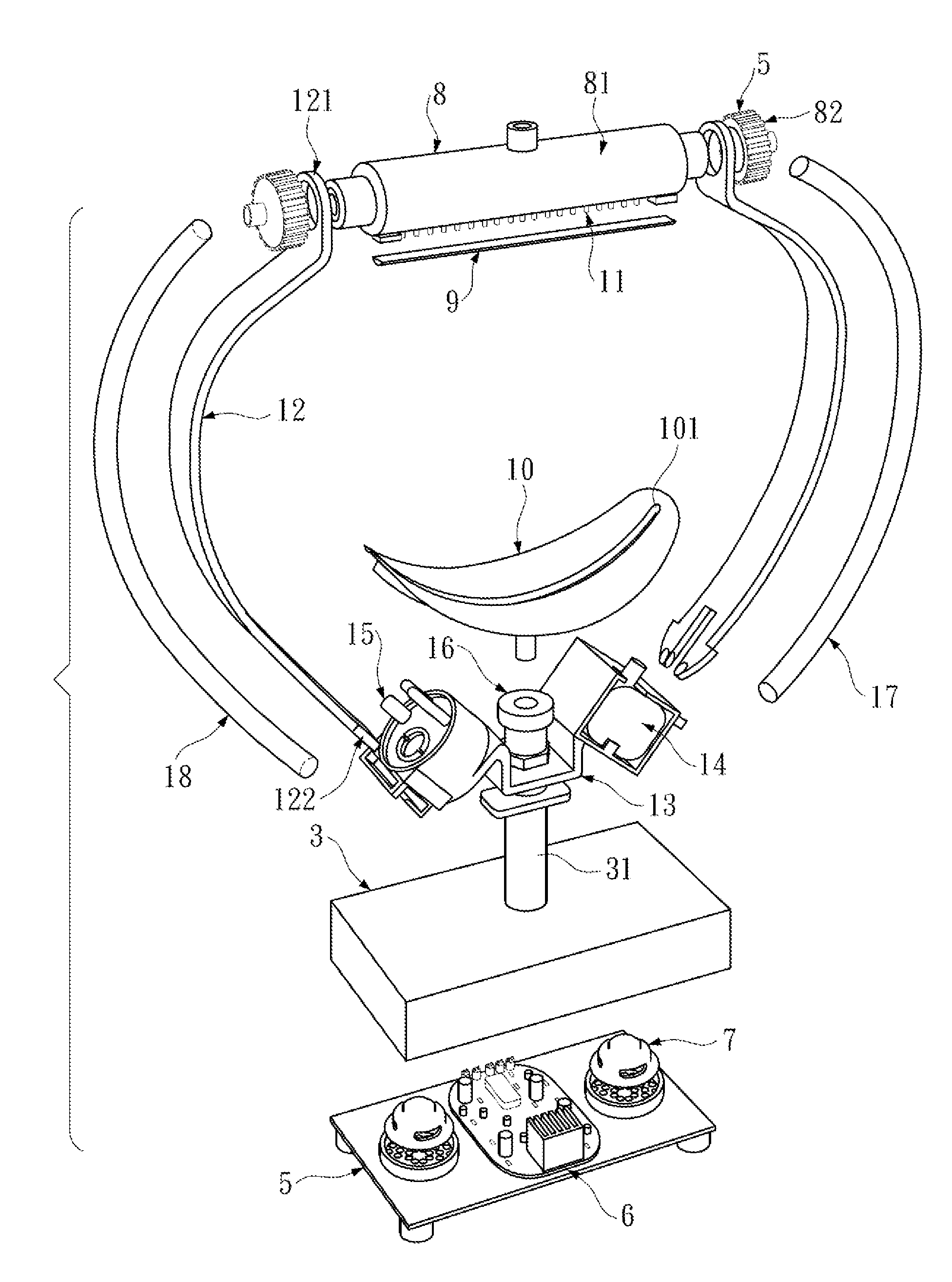
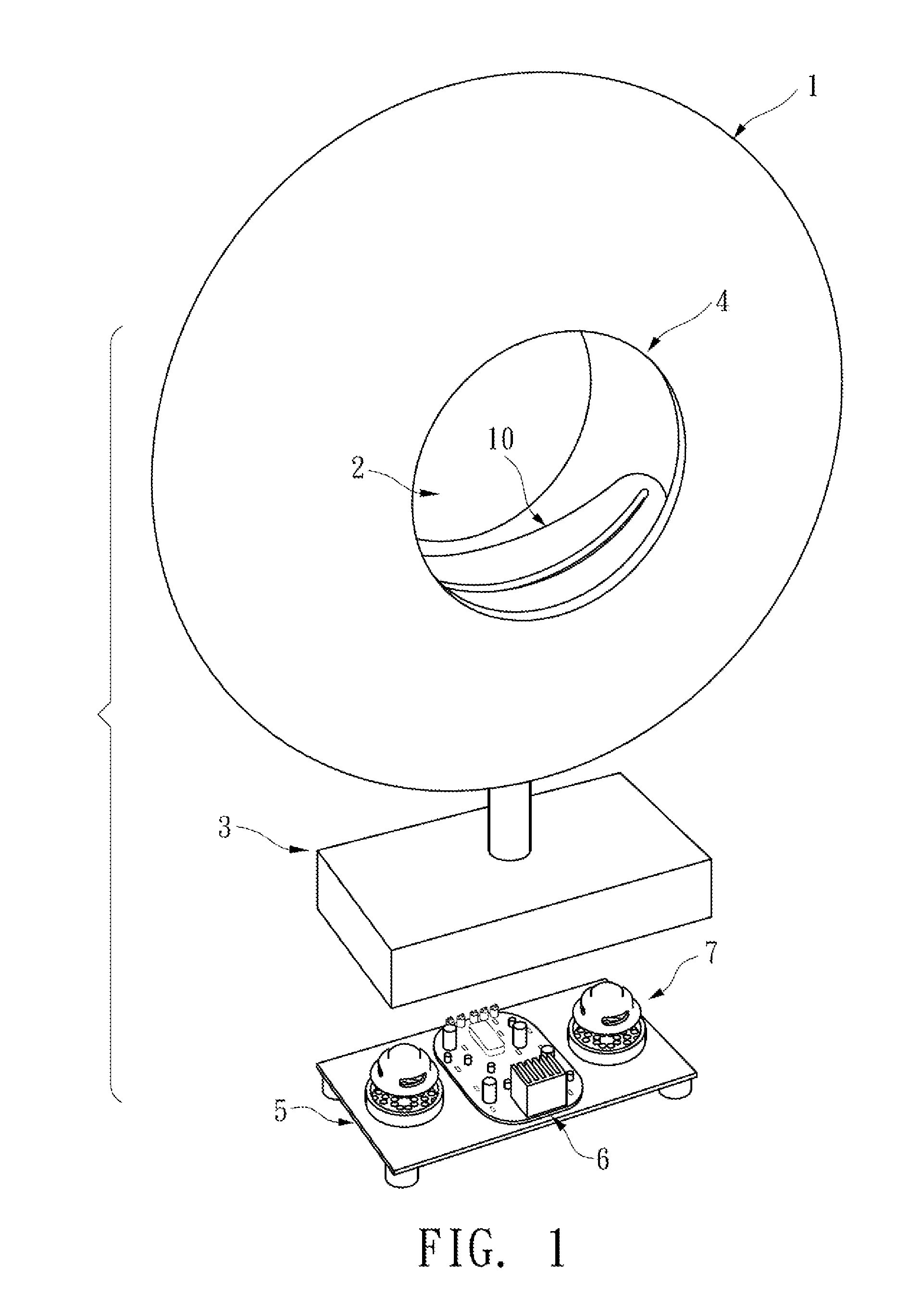
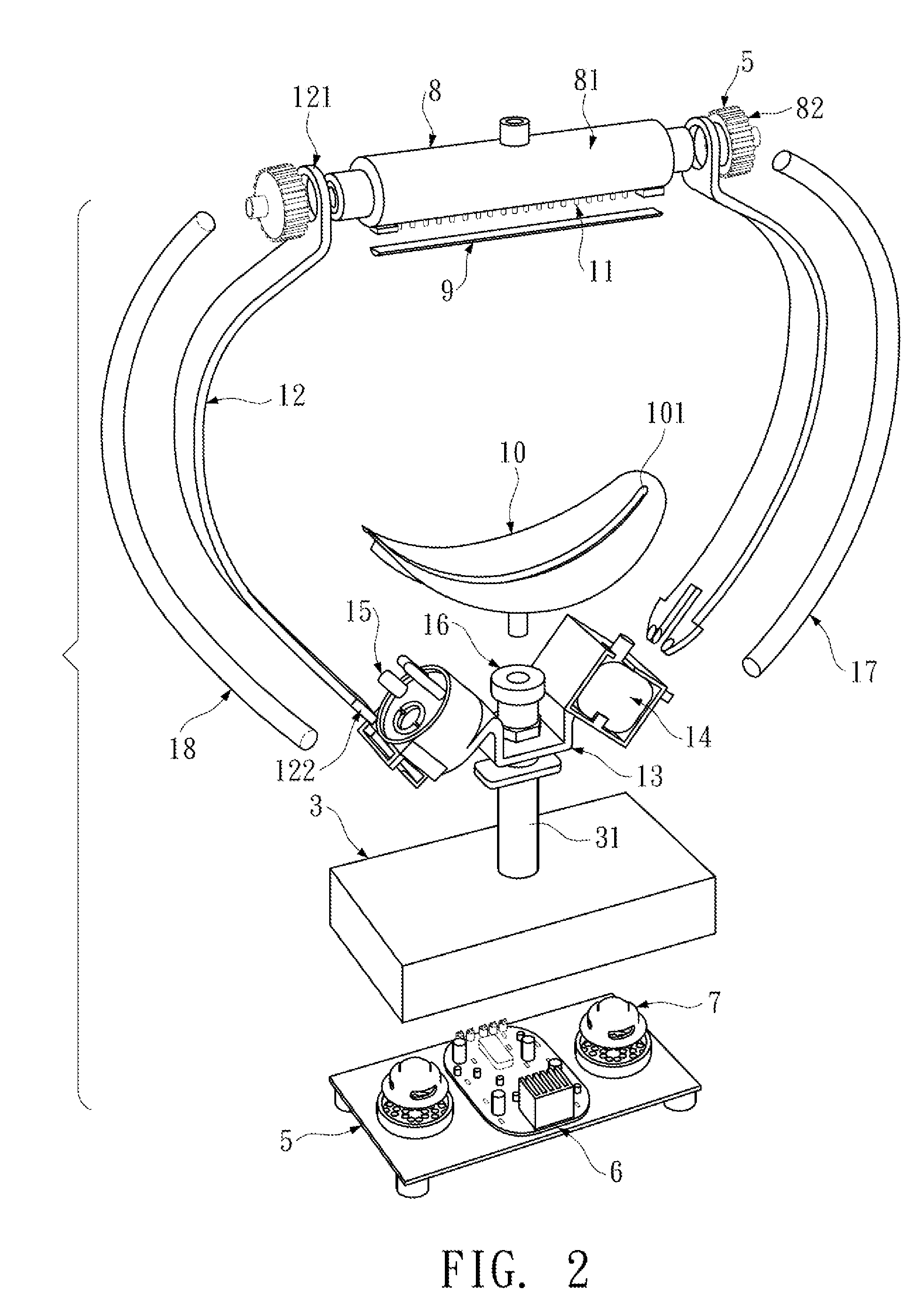
[0016]With reference to FIGS. 1 to 3 for a structure of a wind-water ultrasonic humidifier in accordance with a preferred embodiment of the present invention, the structure is provided for the illustration of the present invention only, but not intended for limiting the scope of the invention.

[0017]In FIG. 1, the wind-water ultrasonic humidifier of the present invention comprises a ceramic housing 1, a water circulation system 2 installed in the housing 1, a bottom base 3 disposed at the bottom of the humidifier and a circuit retaining board 5 installed in the bottom base. The bottom of the bottom base 3 is a hollow structure for containing the circuit retaining board 5, and the middle of the top of the bottom base 3 has an opening interconnected with a hollow connecting portion, and the top of the hollow connecting portion has an externally threaded circular pipe 31 passed through a support plane with a circular hole at the bottom of the housing 1 and extended into the hollow housi...


PUM


Abstract

A wind-water ultrasonic humidifier includes a housing, a hollow connecting portion, a water circulation system, and a power control box. The water circulation system includes an electric base, a rubber cork plugged into the top of the water circulation system and having a baffle inserted into a concave hole, a circular threaded pipe including a nebulizer and a water pump, two arc-shaped bridging support stands provided for connecting both sides of the electric base in an arc shape, a latch structure disposed at a lower end of the support stand, latches disposed on both sides of the electric base, and a water dripping device installed at an upper end of the bridging support stand.

Description

BACKGROUND OF THE INVENTION[0001]1. Field of the Invention[0002]The present invention relates to a wind-water ultrasonic humidifier.[0003]2. Description of the Related Art[0004]Present existing ultrasonic humidifiers generally require a fan to blow mists after water dripping and nebulization processes take place, and thus consume much electric power. Furthermore, the conventional ultrasonic humidifiers lack of artistic decorative appearance, expansion function, and fun.SUMMARY OF THE INVENTION[0005]Therefore, it is a primary objective of the present invention to overcome the aforementioned shortcoming and deficiency of the prior art by providing a wind-water ultrasonic humidifier designed with a wonderful concept and a bold innovation, and adopting a ceramic housing with simple, and fashioned decoration instead of the traditional dull and boring housing. As to the structure and functions of the wind-water ultrasonic humidifier, wonderful structure and circuit control are used for si...

Claims


Application Information

Patent Timeline
Patent Type & Authority Applications(United States)
IPC IPC(8): B01F3/04B05B1/08
CPCA61M11/005Y02B30/80A61M21/02A61M2021/0044B05B1/20F21S10/02F24F6/12F24F2006/001F24F2006/125F24F2011/0068F24F2221/02F24F2221/12Y10S261/48Y10S261/14A63J5/025A63J17/00A61M11/02F24F11/56Y02B30/70
Inventor CHEN, HUI-CHIN
Owner CHEN HUI CHIN
Learn More