
Method of Correlating Known Image Data of Moving Transmitters with Measured Radio Signals

a technology of radio signals and image data, applied in the direction of direction finders, radio wave direction/deviation determination systems, instruments, etc., can solve the problems of transmitter frequency drift, carrier fc may be unknown, transmitter transmission frequency may be generally unknown

Active Publication Date: 2011-03-31
RINCON RES CORP
View PDF17 Cites 103 Cited by
  • Summary
  • Abstract
  • Description
  • Claims
  • Application Information

AI Technical Summary

Benefits of technology

[0081]Certain embodiments allow for radio transmissions to assist associating image track segments with moving transmitters despite momentary breaks in image visibility of the moving transmitter. In other words, in certain embodiments, the measured radio data can be used to fill in information gaps about vehicle position in the image data if the image data becomes discontinuous. In other embodiments, vehicles that cease transmitting may be followed by continuing to image them.

Problems solved by technology

Unfortunately, when the task is to locate an unknown transmitter, the transmitted waveform may be unknown, and what is more, may not a simple waveform, i.e., may not include a simple sinusoidal carrier waveform of a single frequency.
In certain situations the carrier Fc may be unknown, and may drift with time due to transmitter oscillator instability.
Unfortunately, the transmitter's transmission frequency is generally unknown, for example, because of manufacturing tolerances.
Additionally, the frequency of the transmitter may drift over time.
This complicates the problem, moving the number of unknowns from 2, x and y position, to 3 to 4 unknowns.
This problem was complicated by the fact that ship motion introduced additional unknown parameters, i.e., the ship's course and speed, which affected the Doppler measurements.
Computation of the cross-ambiguity function generally requires electronic hardware or software, however, there is nothing in principle that dictates that a cross-ambiguity function must be computed with either analog or digital hardware.
The basic problem to be solved by conventional methods is to locate the unknown position of a transmitter on the basis of measurements of received signals by one or more receivers.
Locating non-cooperative transmitters, i.e., transmitters transmitting arbitrary signals, is an important and more difficult problem.
Additionally, while, measurements of FOA, TOA, TDOA, FDOA, and AOA are commonly used in various combinations to located fixed transmitters, there are few easy methods for locating moving transmitters.
This is because moving transmitters introduce additional Doppler shifts that are difficult to distinguish when performing FDOA measurements using moving receivers.
A significant problem, indeed perhaps the most significant problem, in locating moving transmitters is determining their path, or their velocity over time.
Otherwise, one can hope that an inconsistency in data residuals would suggest that the assumption was invalid.
With many changes in course and speed, however, as might be present in a land vehicle, this approach fails.

Method used


Image

  • Method of Correlating Known Image Data of Moving Transmitters with Measured Radio Signals
  • Method of Correlating Known Image Data of Moving Transmitters with Measured Radio Signals
  • Method of Correlating Known Image Data of Moving Transmitters with Measured Radio Signals

Examples


Embodiment Construction

[0089]This invention is described in preferred embodiments in the following description with reference to the Figures, in which like numbers represent the same or similar elements. Reference throughout this specification to “one embodiment,”“an embodiment,” or similar language means that a particular feature, structure, or characteristic described in connection with the embodiment is included in at least one embodiment of the present invention. Thus, appearances of the phrases “in one embodiment,”“in an embodiment,” and similar language throughout this specification may, but do not necessarily, all refer to the same embodiment.

[0090]The described features, structures, or characteristics of the invention may be combined in any suitable manner in one or more embodiments. In the following description, numerous specific details are recited to provide a thorough understanding of embodiments of the invention. One skilled in the relevant art will recognize, however, that the invention may ...


PUM


Abstract

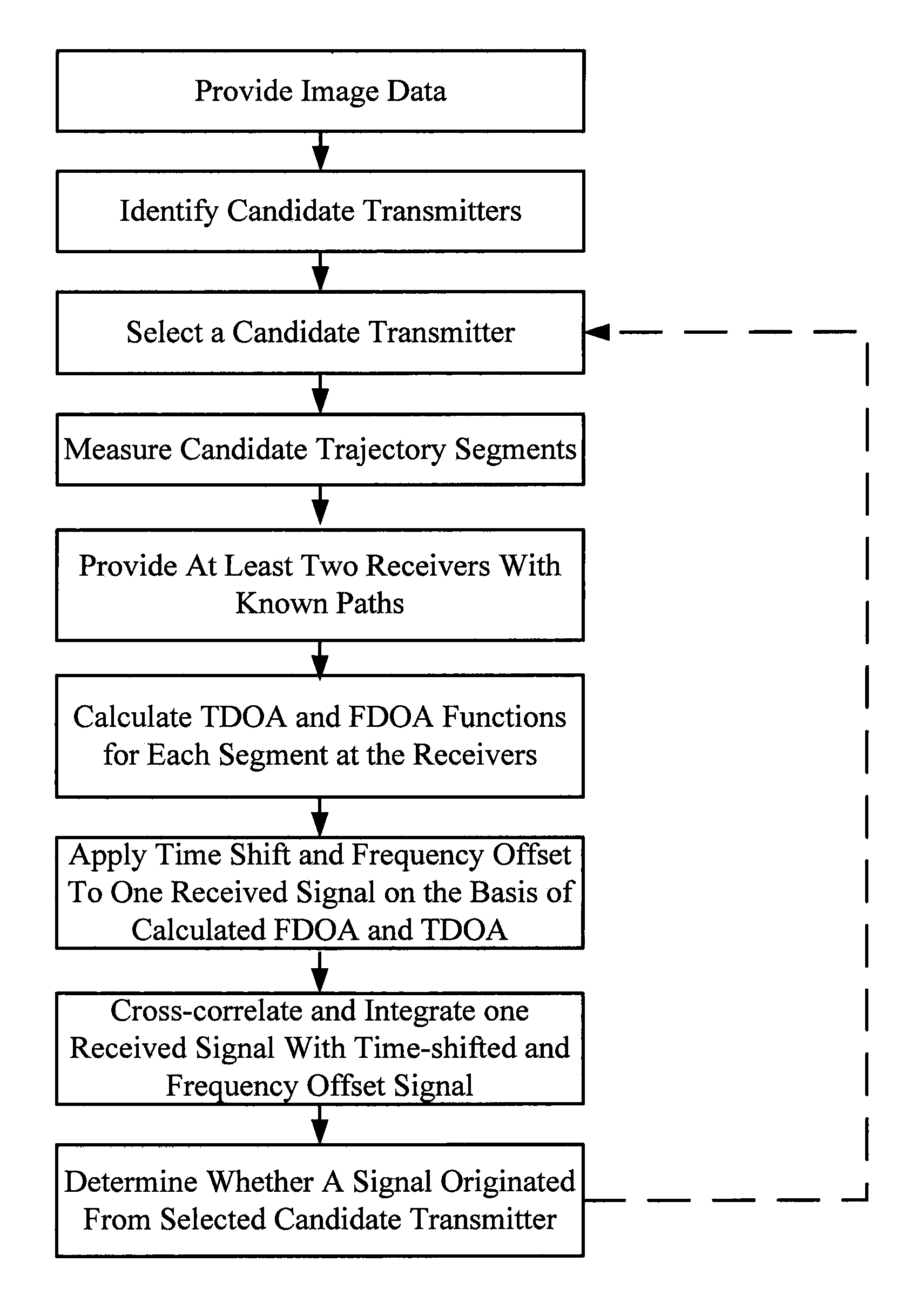
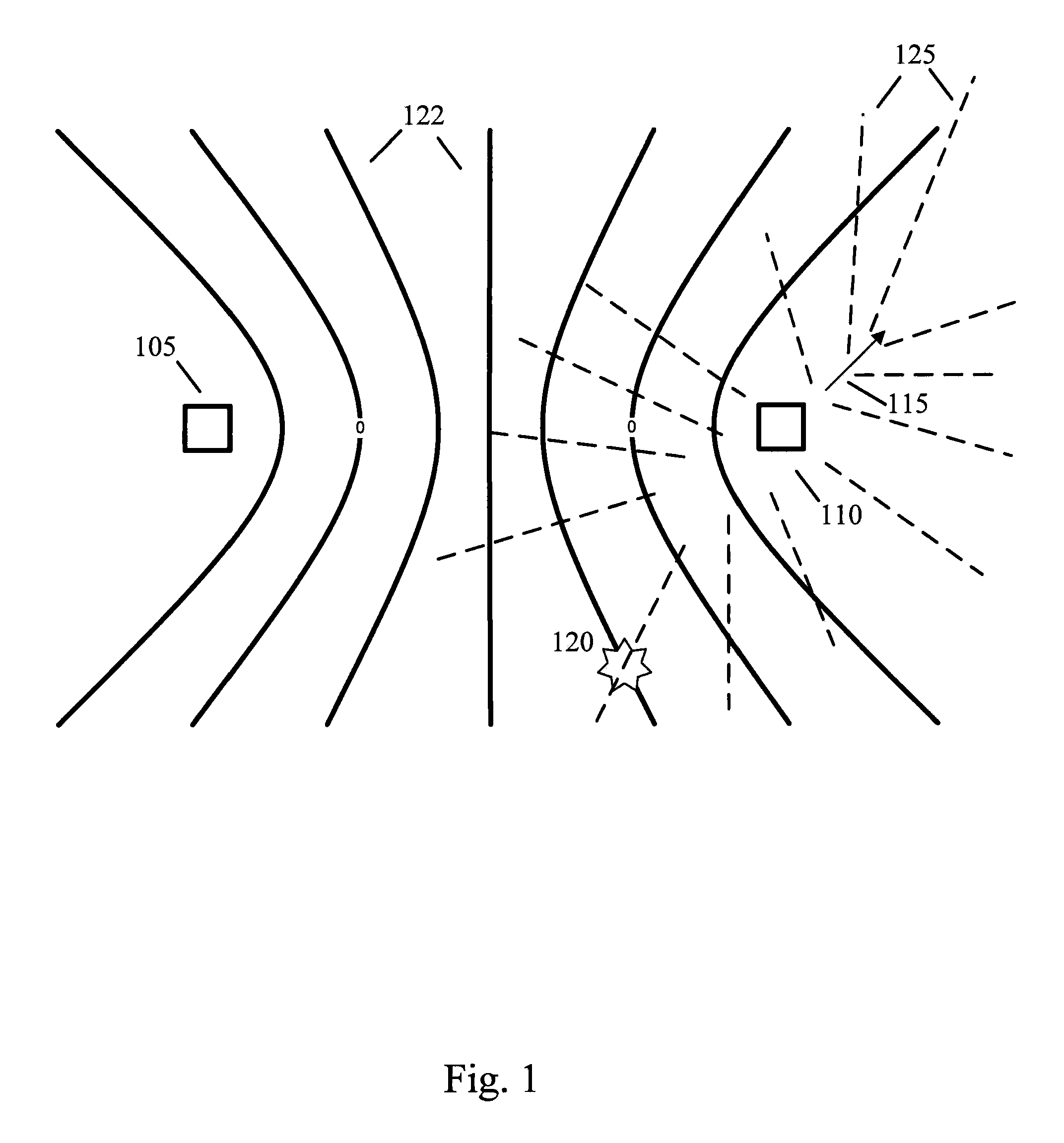
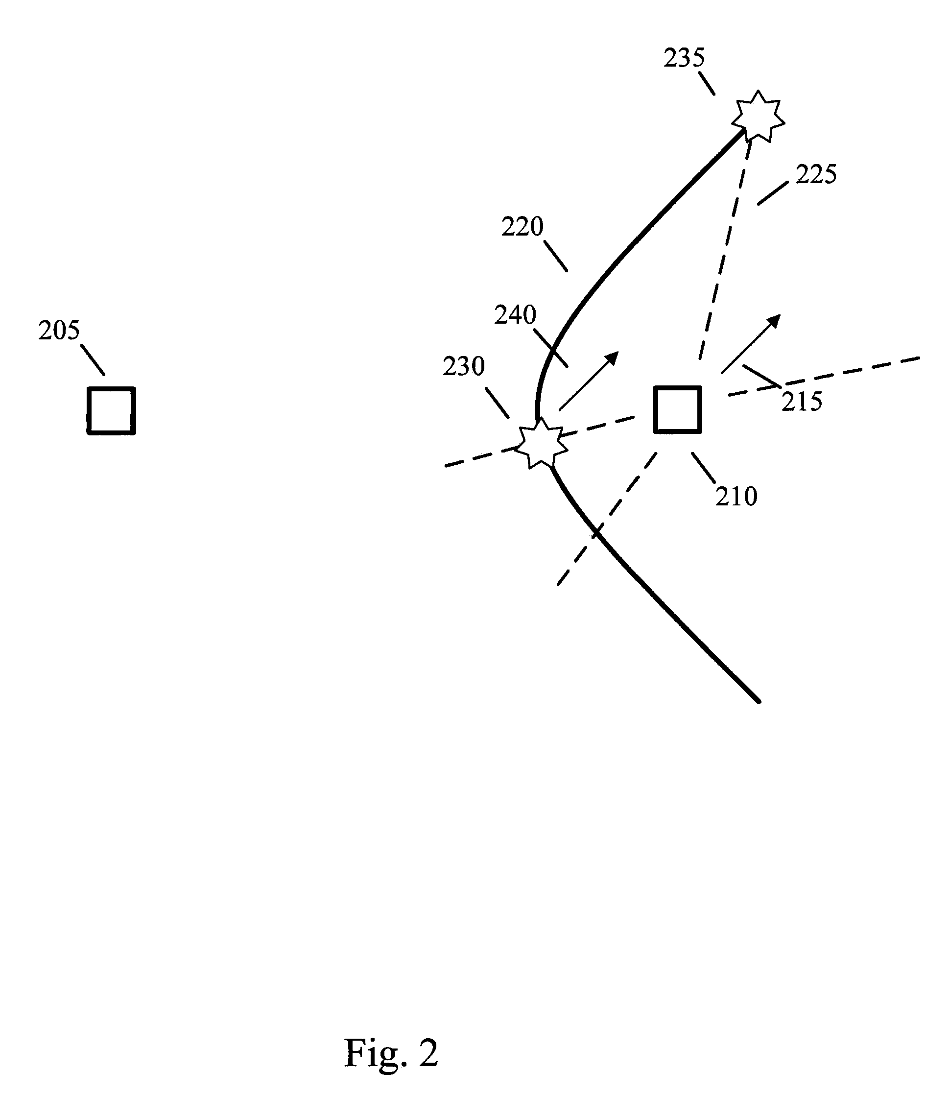
Systems and methods of correlating potential transmitters with received radio signals is provided. Image data is provided including paths traveled by potential transmitter. Potential transmitters are identified within the image data along with path segments traveled by potential transmitters. A first and second transmitter calculate certain parameters of received signals assuming that signals originated along the path segments. The calculated signal parameters are then compared to measured signal parameter to determine whether a transmitter is associated with a particular path.

Description

FIELD OF THE INVENTION[0001]The invention relates generally to radio geolocation techniques and geographical imaging.BACKGROUND OF THE INVENTION[0002]Both known and novel methods exist that use multiple receivers having known locations to solve for the position of unknown transmitters, which can be both stationary and in motion. One novel method geolocating moving or fixed transmitters using time difference of arrival (TDOA) and / or frequency difference of arrival (FDOA) at multiple observing receivers is disclosed in co-pending U.S. patent application Ser. No. 11 / 464,762, the disclosure of which is incorporated herein in its entirety. What is common among these known and novel methods is that they attempt to solve for an unknown transmitter location or path based on signals received at known locations. Disclosed herein is the use of similar principles to solve a somewhat related problem, to wit, assuming that a plurality of potential transmitter paths are known, analyzing signals re...

Claims


Application Information

Patent Timeline
Patent Type & Authority Applications(United States)
IPC IPC(8): G01S3/16
CPCG01S5/16
Inventor PARKER, MICHAEL N.
Owner RINCON RES CORP
Learn More