Supercharge Your Innovation With Domain-Expert AI Agents!

Micromechanical digital capacitor with improved RF hot switching performance and reliability

a micromechanical and digital capacitor technology, applied in the direction of electrostrictive/piezoelectric relays, electrical apparatus, coatings, etc., can solve the problem of capacitive rf mems, and achieve the effect of increasing the release voltag

Active Publication Date: 2011-04-07
QORVO US INC
View PDF19 Cites 14 Cited by
  • Summary
  • Abstract
  • Description
  • Claims
  • Application Information

AI Technical Summary

Benefits of technology

[0015]The present invention generally relates to RF MEMS devices that are capable of hot switching. The RF MEMS devices, by utilizing one or more spring mechanisms, are capable of hot switching. In certain embodiments, two or more sets of springs may be used that become engaged at specific points in the displacement of the cantilever of the MEMS device. The springs allow for a significant increase in the release voltage for a given landing voltage.

Problems solved by technology

The large difference between the release voltage and the landing voltage creates a problem for capacitive RF MEMS when it comes to hot switching.

Method used


Image

  • Micromechanical digital capacitor with improved RF hot switching performance and reliability
  • Micromechanical digital capacitor with improved RF hot switching performance and reliability
  • Micromechanical digital capacitor with improved RF hot switching performance and reliability

Examples


Embodiment Construction

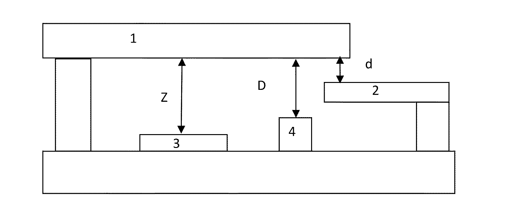
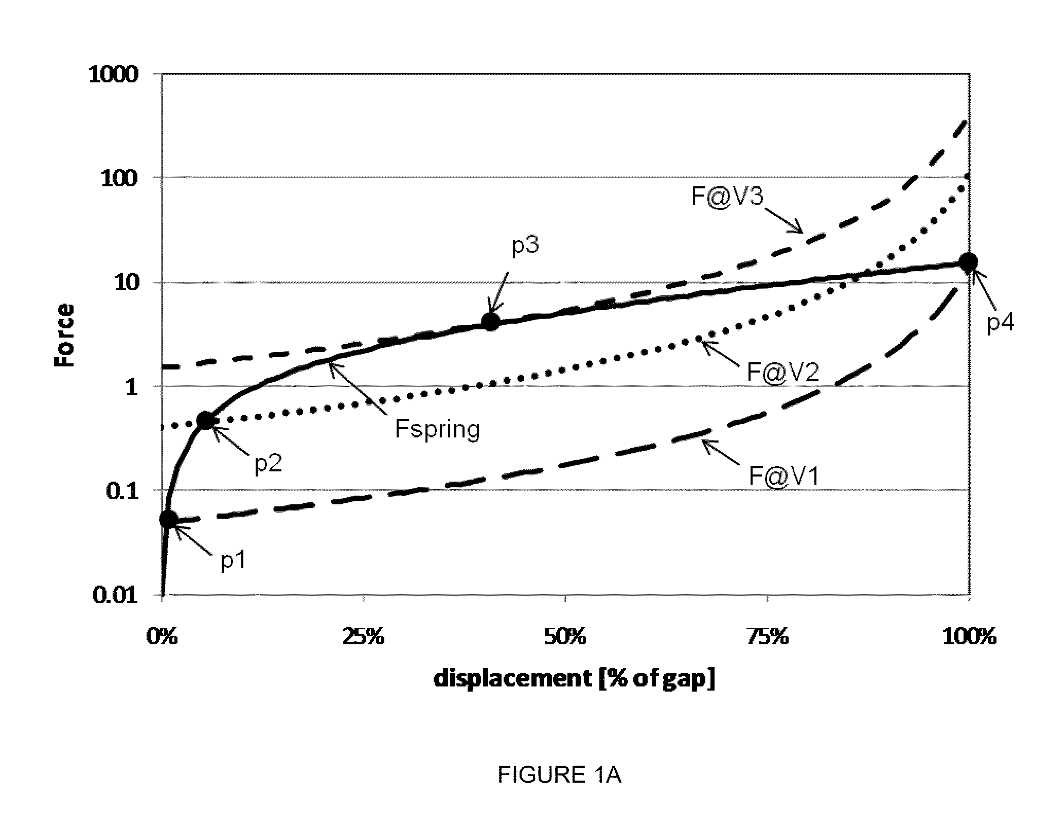
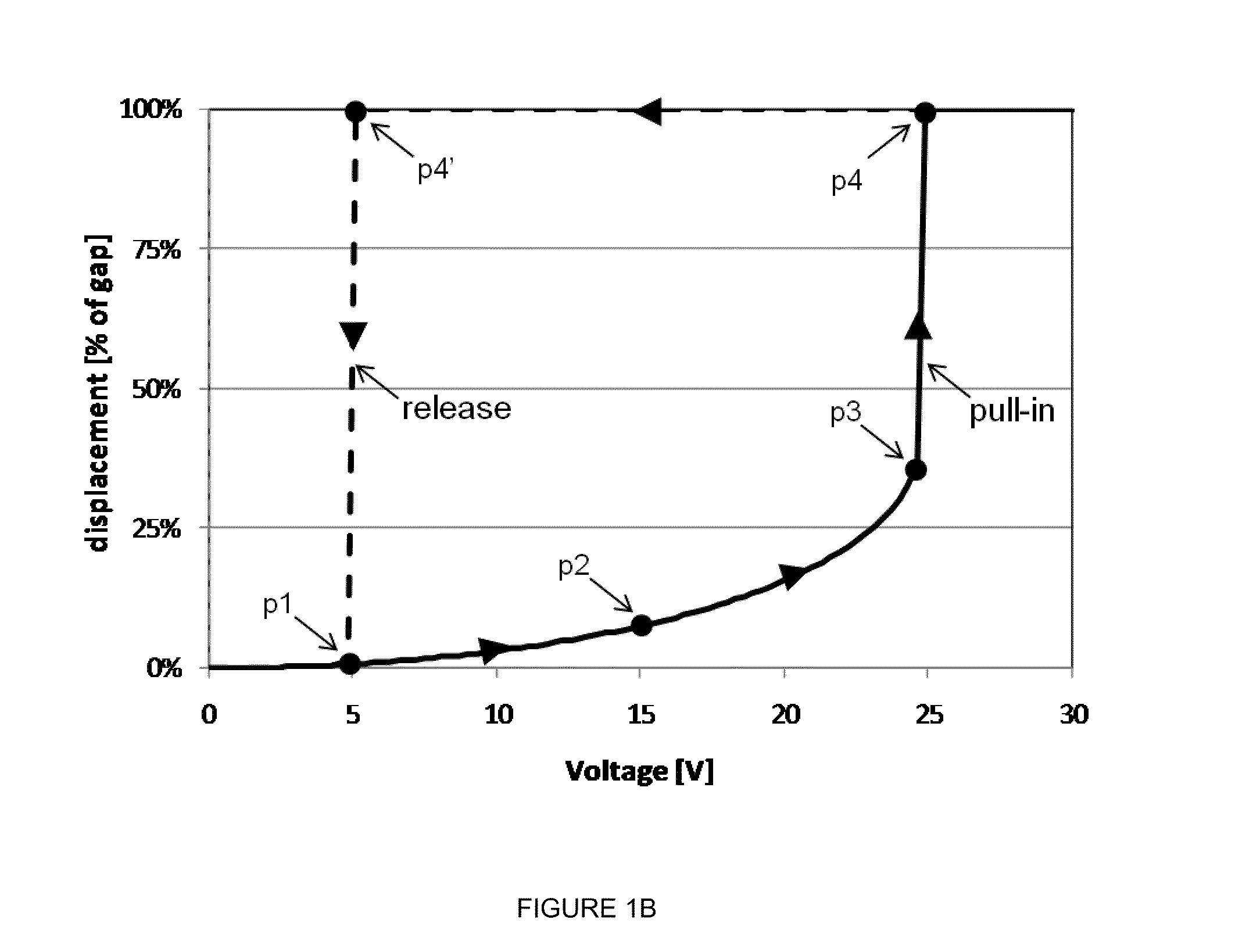
[0048]The present invention uses two or more sets of springs that become engaged at specific points in the displacement. This allows for a significant increase in the voltage that can be applied to the RF electrode for a given pull in landing voltage.

[0049]If the cantilever initially has a spring constant of k1 and then after it has been pulled in a distance d it lands on an additional spring with a spring constant k2, then the spring constant of the combined system has a step wise increase. The second spring 2 can either be on the substrate or it can be attached to the first cantilever (as shown in FIG. 2A and FIG. 2D respectively) and make contact to a bump before the first cantilever makes contact to the substrate or contact. Thus there are two regions of displacement X for the end of the first primary cantilever, firstly from 0 to d where the restoring force is k1*X and then from d to D the restoring force is (k1*X+k2*(X−d)). Here, D is the total movement of the first cantilever...


PUM


Abstract

The present invention generally relates to RF MEMS devices that are capable of hot switching. The RF MEMS devices, by utilizing one or more spring mechanisms, are capable of hot switching. In certain embodiments, two or more sets of springs may be used that become engaged at specific points in the displacement of the cantilever of the MEMS device. The springs allow for a significant increase in the release voltage for a given pull in landing voltage.

Description

CROSS-REFERENCE TO RELATED APPLICATIONS[0001]This application claims benefit of U.S. Provisional Patent Application Ser. No. 61 / 247,852 (CK064L), filed Oct. 1, 2009, which is herein incorporated by reference.BACKGROUND OF THE INVENTION[0002]1. Field of the Invention[0003]Embodiments of the present invention generally relate to the field of micromechanical variable capacitors, specifically to the act of releasing a digital capacitor in the presence of a residual RF voltage. The inventions described herein can be applied to any micromechanical structure where the difference between latching voltage and actuation voltage needs to be minimized. It allows devices to be made where the spring constant of the cantilever can be engineered to be greater than the electrostatic attraction across the landing contact due to the voltage dropped across the capacitance contact, while the voltage required to turn the device on is unchanged.[0004]2. Description of the Related Art[0005]Micromechanical ...

Claims


Application Information

Patent Timeline
Patent Type & Authority Applications(United States)
IPC IPC(8): H01H59/00B05D5/12
CPCH01G5/18H01H59/0009
Inventor KNIPE, RICHARD L.VAN KAMPEN, ROBERTUS PETRUSUNAMUNO, ANARTZ
Owner QORVO US INC
Features
  • R&D
  • Intellectual Property
  • Life Sciences
  • Materials
  • Tech Scout
  • Unparalleled Data Quality
  • Higher Quality Content
  • 60% Fewer Hallucinations
Learn More